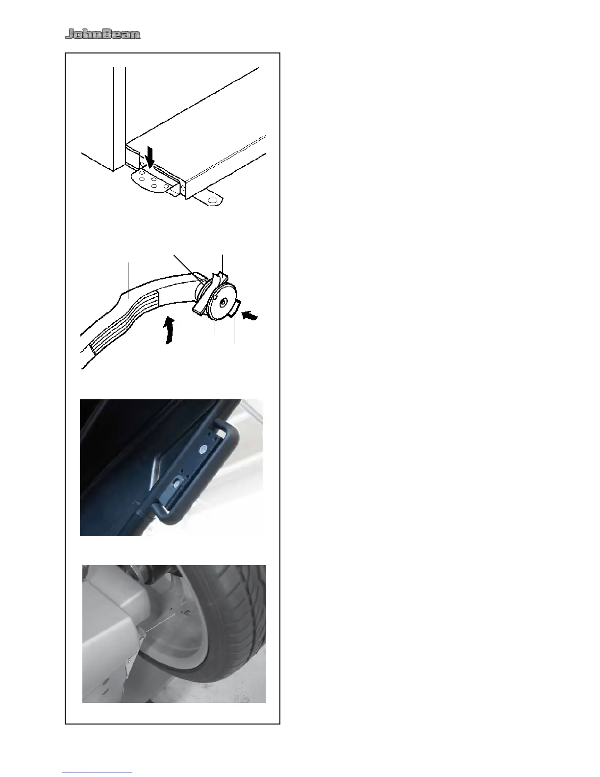
Fig. 4-16 Pedal of main shaft lock
The main shaft is locked when the pedal is depressed.
This facilitates tightening or untightening of the
clamping nut and retains the wheel in the correction
position for correct tting of the balance weights.
Note:
This lock is designed only to facilitate orientation
of the wheel and must not be used for braking the
main shaft.
Depress the pedal to actuate the main shaft lock,
thus locating the main shaft.
4.5 Gauge arms
Fig. 4-17 Gauge arm for distance and rim diameter
1 Gauge arm, can be extended and hinged upwards
2 Weight holder to locate the adhesive weight both
for identication of subsequent tting position and
for actual tting of the balance weight
3 Adhesive weight held in weight holder
4 Gauge head to identify rim dimensions on a
variety of rim proles
5 Spring-suspended applicator.
4.6 Ultrasonic detector
On the outer side of the rim the machine has an
ultrasound detector for the wheel width (outside of
rim) (Fig. 4-17b).
4.7 Laser Pointer
Figure 4-18
The machine uses the Laser Pointer to indicate the
precise point for tting the adhesive weights on the
rim ( 5.8).