System 450™ Series Control Module with Ethernet Communications Installation Instructions
34
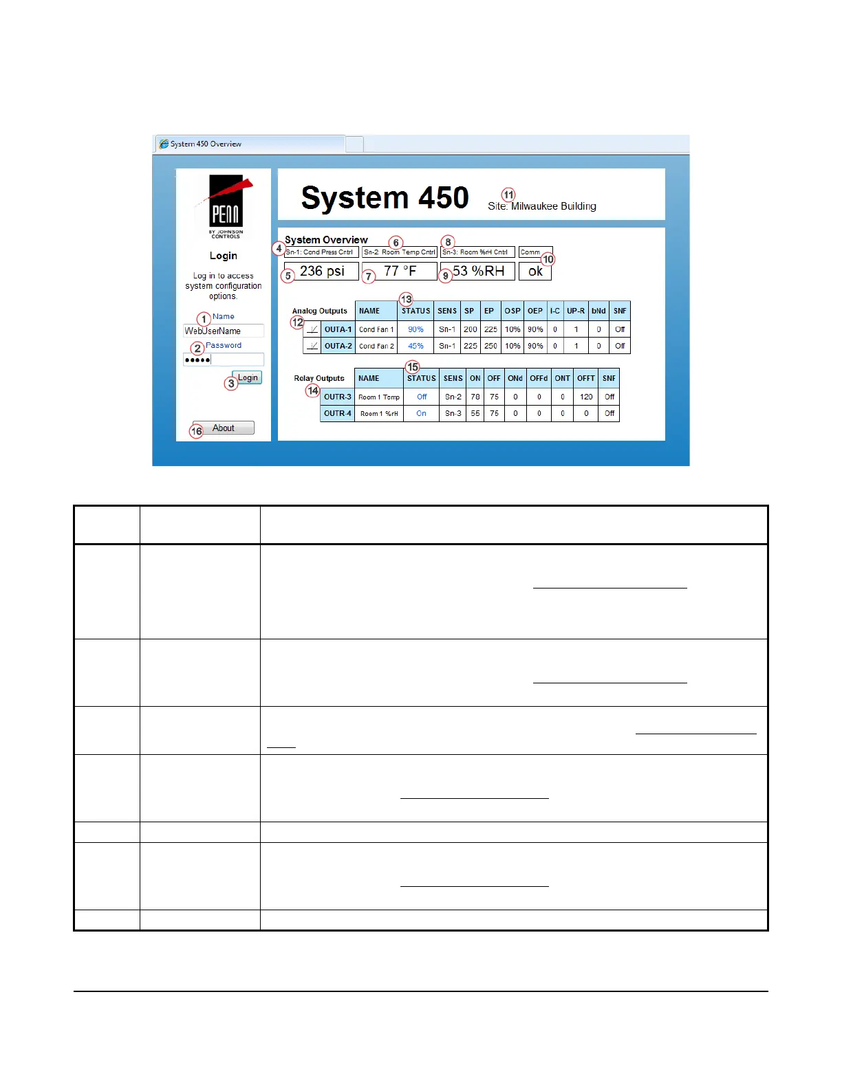
Table 14 provides descriptions, user actions, and references for the items called out in Figure 8.
Table 14: System 450 Web UI Overview Page Descriptions, User Actions, and References (Part 1 of 2)
Callout
Number
Identifier
Item Name
User Actions, Descriptions, References
1Name
Login Field
Enter the assigned System 450 web username here.
Note: You can assign a web username in the WebUserName: field in the Web Server
section on the Network Configuration page. See Network Configuration Page
on page 47
for more information about assigning a username.
In this example, WebUserName is entered as the assigned login name. The default web
username is System450User1.
2 Password
Login Field
Enter the assigned System 450 web password here.
Note: You can assign a web password in the Web Password: field in the Web Server
section on the Network Configuration page. See Network Configuration Page
on page 47.
In this example, a password is entered. The default web password is Wx9jc3.
3Login
Button
After entering the assigned web username and web password, click Login to log in to the
System 450 web UI. The System Configuration page appears. See System Configuration
Page on page 35 for more information.
4Sn-1:
Sensor 1 Name
Identifies the Sn-1 (Sensor 1) and displays the assigned Sn-1 name.
Note: You have the option to assign a sensor name for Sn-1 in the Name field in the Sn-1:
Sensor 1 section on the Sensor Configuration Page
on page 37.
In this example, the assigned sensor name for Sn-1 is Cond Press Cntrl.
5 Sn-1 Status Displays the current condition status sensed at Sn-1.
6Sn-2:
Sensor 2 Name
Identifies the Sn-2 (Sensor 2) and displays the assigned Sn-2 name.
Note: You have the option to assign a sensor name for Sn-2 in the Name field in the Sn-2:
Sensor 2 section on the Sensor Configuration Page
on page 37.
In this example, the assigned sensor name for Sn-2 is Room Temp Cntrl.
7 Sn-2 Status Displays the current condition status sensed at Sn-2.
Figure 8: System 450 System Overview Page Example
 Loading...