5396713-BIM-C-0319
4 Johnson Controls Ducted Systems
SECTION IV: ELECTRIC FURNACE
INSTALLATION
7900 SERIES DUCT CONNECTOR FOR EBE DOWN-
FLOW
The duct connector is designed to eliminate a sub-base requirement.
Table 1 provides the part number of the duct connector needed.
Provide adequate clearance for servicing.
1. Locate furnace conveniently away from wall facing or partitions to
permit easy removal of components.
2. A six (6) inch space minimum should be maintained between the
furnace and closet door when door is used for return air.
3. Two (2) feet of space must be available in front of furnace for
future servicing (blower, element or furnace removal, etc.).
- Indicates connector above or below could be used depending on tolerance
in floor to duct dimension.
- Indicates connector above could be used depending on tolerance in floor
to duct dimension.
- Indicates connector below could be used depending on tolerance in floor to
duct dimension.
DUCT CONNECTORS (7990 SERIES)
These duct connectors are for connecting the furnace to an under the
floor supply duct system. The furnace may be installed on combustible
flooring without a separate sub-base.
TABLE 1:
Duct Connector for Electric Furnaces
FLOOR TO
DUCT DIMENSIONS
FINGERED
STYLE
SCREW
TAB STYLE
1” (2.54 cm) 7990-6211 7990-6011
2” (5.1 cm) 7990-6221 7990-6021
3” (7.6 cm)
4” (10.2 cm) 7990-6241 7990-6041
5” (12.7 cm)
6” (15.2 cm) 7990-6261 7990-6061
7” (17.8 cm) 7990-6271 7990-6071
8” (20.3 cm) 7990-6281 7990-6081
9” (22.8 cm)
10” (25.4 cm) 7990-6301 7990-6101
11” (282 cm)
12” (30.5 cm) 7990-6321 7990-6121
13” (33 cm)
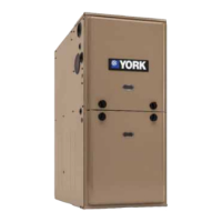
FIGURE 4: Duct Connector Depth (7990 Series)
DUCT CONNECTOR
DEPTH
FLOOR
FLOOR
JOIST
SUPPLY DUCT
A0867-001
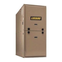
FIGURE 5: Duct Connector Dimensions (7990 Series)
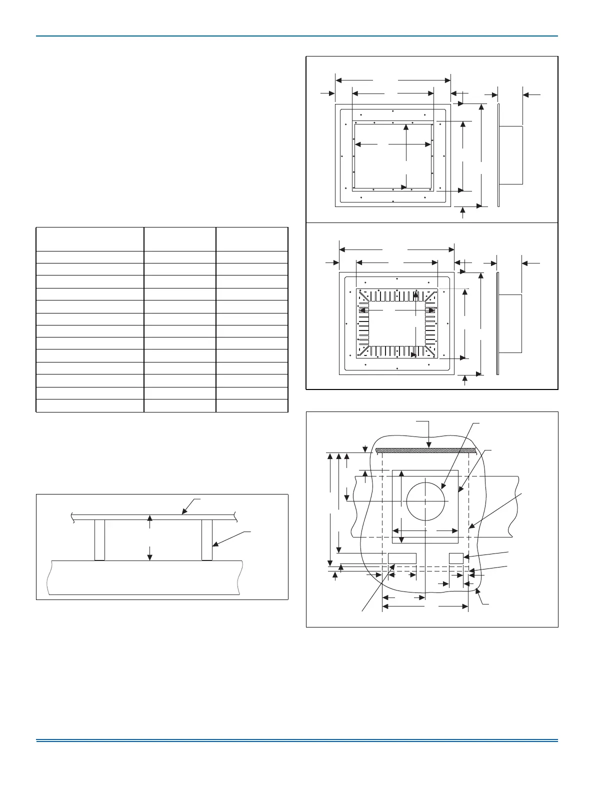
FIGURE 6: Recommended Floor Cut-out (7990 Series)
12
13
11
14
See
Chart
18-3/4
18-3/4
2-3/8
4-3/8
2-3/8
DUCT CONNECTORS FOR
SCREW ATTACHMENT
2-3/8
A0868-001
.
13
11
14
See
Chart
12
DUCT
CUTOUT
DIMENSIONS
DUCT CONNECTORS FOR
TAB ATTACHMENT
18-3/4
2-3/8
18-3/4
2-3/8
4-3/8
A0869-001
2-3/8
2-3/4
MIN.
23-1/4
20-1/2
9-7/8
2-1/8
1-3/8
6-3/8
9-3/4
20
3-1/4
1-1/8
15
15
1
REAR WALL
OF ENCLOSURE
CEILING CUT-OUT
FOR ROOF JACK
FLOOR CUT-OUT
FOR DUCT
CONNECTOR
FURNACE
OUTLINE
OPTIONAL
ELECTRIC
ENTRANCE
FLOOR
FUTURE
REFRIGERANT
LINE ENTRANCE
A0875-001