5396713-BIM-C-0319
6 Johnson Controls Ducted Systems
WIRING
Furnace wiring is complete except for the power supply and the thermo-
stat wires. See wiring diagrams (Figures 13–18) for wire and fuse size.
See Table 2 for ground wire sizes. Thermostat wires connect through
side of furnace and should also be no smaller than 22 gauge. Power
wires can enter through the side of the unit or through the auxiliary
entrance, located in the bottom of the unit. (See Figure 1). When bring-
ing wiring through the bottom of the furnace, cable connectors must be
installed to hold wiring in place and to relieve any strain on the wiring.
These connectors also serve as a seal between the furnace and the
floor. Thus, additional sealing is not required.
Refer to the National Electrical Code, Canadian Electrical Code and
local codes for wiring material requirements.
Models for EBE/EUE15*, EBE/EUE17*, EBE/EUE20*, and EBE/
EUE23* may be connected to a single or dual branch circuit.
These units are shipped from the factory set up for dual power supply
connections. For single power supply connections, jumper bars (P/N
3500-378P*) are required and are available from the factory. See Fig-
ures 11 and 12.
NOTICE
The furnaces are equipped with either one or two 60 amp circuit
breakers. These circuit breakers protect the wiring inside of the fur-
nace in the event of a short circuit. Additionally, these breakers pro-
vide a means of disconnecting the power to the unit. The circuit
breakers in the furnace are not meant to protect the branch circuit
wiring between the furnace and the home's breaker panel. General
wire and breaker sizes are shown in Table 2. If sheathed cable is
used, refer to National Electrical Code, Canadian Electrical Code
and local codes for additional requirements concerning supply cir-
cuit wiring. Electrical Data can be found in Table 4.
IMPORTANT
All installation on field wiring must be rated at 60ºC or higher.
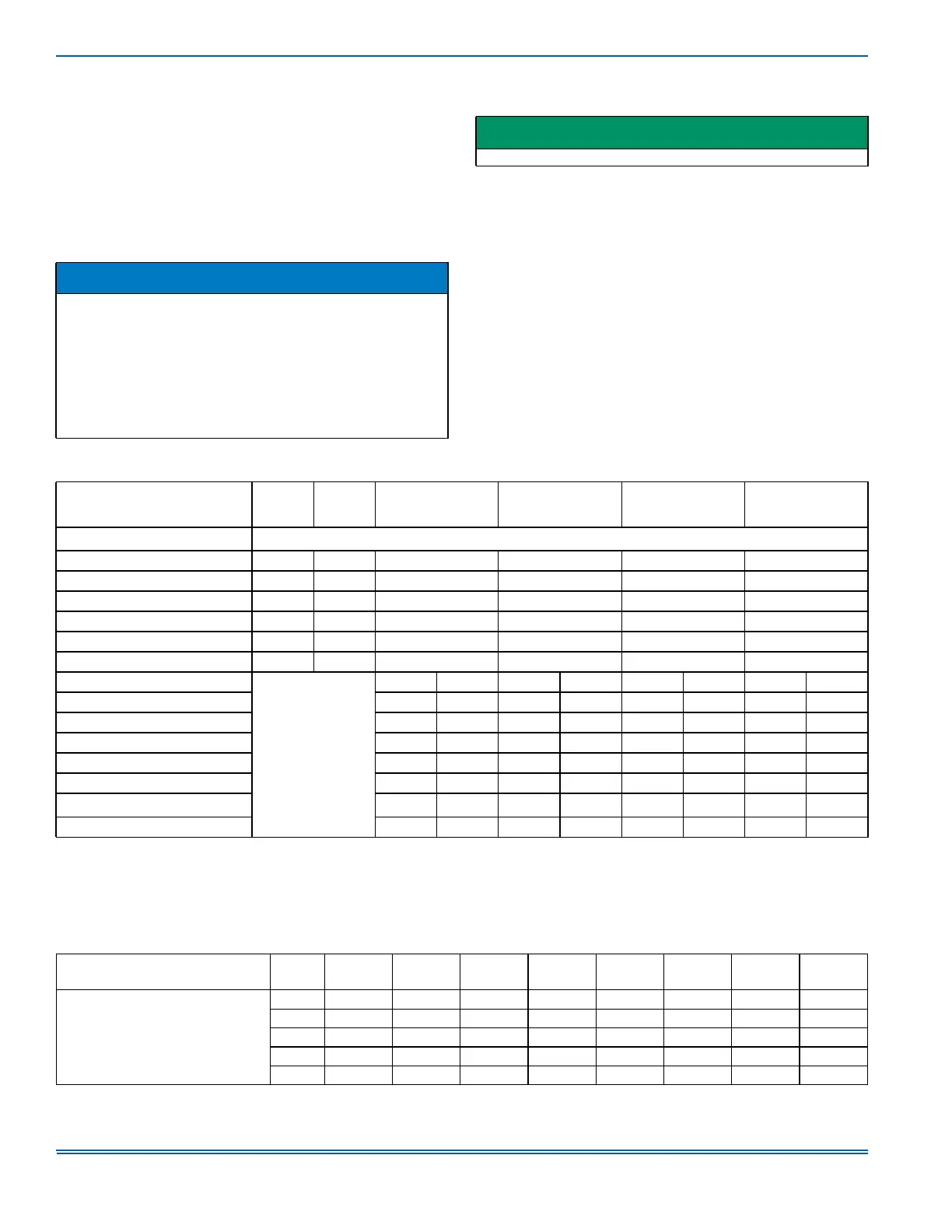
TABLE 2:
Wiring Requirements
MODELS
1
EBE10A
EUE10A
1. Does Not require a Jumper.
2
EBE12A
EUE12A
2. Jumper provided for Single Branch Circuit Only.
3
EBE15A
EUE15A
3. Requires Jumper Bars (P/N 3500-378P).
3
EBE17A
EUE17A
3
EBE20A
EUE20A
3
EBE23A
EUE23A
Single Branch Circuit Service 2 Leads + 1 Ground CKT #1
Nominal Circuit Load - Amps 43.8 50.5 63.8 70.4 83.8 93.8
Minimum Wire Size (90ºC) #8 #6 #4 #4 #3 #2
Minimum Wire Size (75ºC) #6 #6 #4 #3 #2 #1
Minimum Wire Size (60ºC) #6 #4 #3 #2 #1 #0
Ground Wire Size + #10 #8 #8 #8 #6 #6
Max. Fuse (or C.B.) - Amps 60 70 80 90 110 125
Dual Branch Circuit Service
NOT
APPROVED
CKT #1 CKT #2 CKT #1 CKT #2 CKT #1 CKT #2 CKT #1 CKT #2
Branch Circuit Load - Amps 43.8 20.0 47.1 23.3 43.8 40.0 47.1 46.7
Branch Circuit Min. - Amps 54.8 25.0 58.9 29.1 54.8 50.0 58.9 58.4
Minimum Wire Size (90ºC) #8 #10 #6 #10 #8 #8 #6 #6
Minimum Wire Size (75ºC) #6 #10 #6 #10 #6 #8 #6 #6
Minimum Wire Size (60ºC) #6 #10 #4 #10 #6 #6 #4 #4
Ground Wire Size
4
4. Refer to National Electrical Code (NEC). Table 250-122 for Non-Sheathed Conductor Ground Wire.
#10 #10 #10 #10 #10 #10 #10 #10
Max. Fuse (or C.B.) - Amps 60 30 60 30 60 50 60 60
NOTES:
TABLE 3:
EBE/EUE Series Blower Performance
Static Pressure
(inches of w.c.)
Speed 0.1 0.2 0.3 0.4 0.5 0.6 0.7 0.8
CFM (STD. Air)
for all EBE/EUE Models
Hi
1607 1563 1515 1477 1434 1406 1377 1345
MH
1390 1346 1298 1286 1253 1224 1201 1160
M
1241 1192 1151 1115 1097 1074 1032 1000
ML
1099 1051 1002 979 949 912 872 855
Lo
1006 950 923 896 860 826 800 728