2 EDA-2040/ATP-2040 Electric Damper Actuator Installation Technical Bulletin
S
etting Actuator Stroke
To set the actuator stroke:
1. Make sure that the damper blade is visually
accessible or its position is permanently marked
on the end of the damper shaft as shown in
Figure 1.
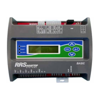
Figure 1: Damper Position Icons
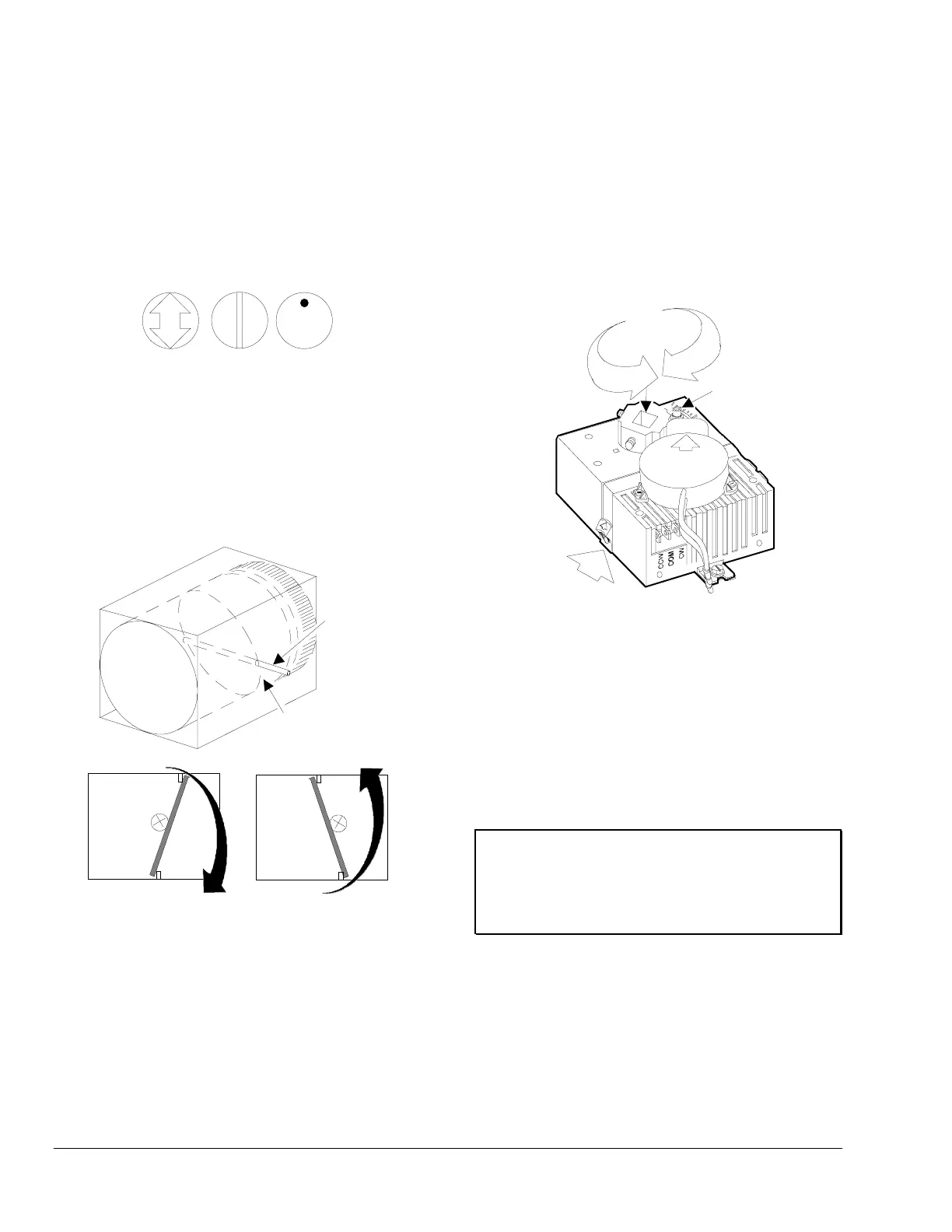
2. Grasp the damper shaft firmly with a pliers and
manually turn the damper in the direction of the
desired close off as shown in Figure 2. Consult
the box manufacturer’s information. Note the
rotation travel (30 to 90 degrees) and direction,
either Clockwise (CW) or Counterclockwise
(CCW), that is required to close the damper.
CW to
Open
CCW to
Open
Damper
Shaft
VAV Box
Damper
Blade
Figure 2: Damper Rotation
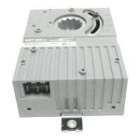
3. Be aware that some box manufacturers do not
use 90 degree rotation. If the damper rotation is
less than 90 degrees, use a 9/64 in. hex key to
loosen the adjustable CCW end-stop on the
EDA-2040 enough to allow movement. Position
the end-stop as required by the application.
(See Figure 3.)
To CW
End-stop
To CCW
End-stop
Ad
ustable
End-stop
OUT
GND
IN
(-) L O
DPT-2015-0
UP
Pu
s
h
Gear
Release
Figure 3: Positioning to the End-stop
Note: Do not excessively loosen the end-stop as
this may permanently disable the
adjustment.
4. Tighten the end-stop between 20 and 25 in·lb.
5. Lift and hold the manual release lever, and turn
the actuator coupler until it contacts the
mechanical stop. Verify that both set screws are
accessible for tightening later.
IMPORTANT: The manual gear release lever will
not function if the actuator is driven
against a stop. Drive the actuator
1 degree off the stop to allow the
release to function.
Note: If the damper closes in the CCW direction,
the coupler should be rotated to the CCW
mechanical limit. If the damper closes in the
CW direction, the coupler should be rotated
to the CW mechanical limit.
6. If the damper shaft is longer than 2-1/4 inches,
use the standard mounting procedures. If the
damper shaft is shorter than 2-1/4 inches, use
the flush mounting procedures.