FIRECLASS Fire detection system Obtain Slot Card Addresses
Installation Guide Doc. version 2.0 29
11.1 Obtain Slot Card Addresses
When you install slot cards as described in later sec-
tions of this guide, you may need to set the addressing
DIP switches of these cards.
Here is an example of how to obtain the address to set:
1 Start the configuration software, we will assume
this is FireClass Express.
2 Open the system configuration.
3 Go to ‘Point Regions’.
4 Look down the list to the ‘Slot Card’ entries.
5 Find a slot address number that is populated with
the type of card you are installing (a PLX800 for
example). There is a maximum of 1 PLX800 slot card
and 1 PNI800 slot card fitted. The addresses are:
PLX800: address 1
PNI800: address 2
6 Make sure this address number has not already
been allocated – you might have to read the DIP
switch settings of already installed cards.
7 If the address number is free, note this to be set on
the card’s DIP switch, as covered in a later section
below.
12 Install the PLX800 - Loop
Expansion Card
1 Assemble the slot card components as shown in
Fig. 24.
2 Check whether the card needs a firmware upgrade
and if so, refer to the relevant Technical Information
Bulletin (TIB).
3 Obtain the address number to set on the card’s
addressing DIP switch – see Section “Obtain Slot
Card Addresses”. For PLX800, the address number
is 1 and there can be a maximum of one PLX800 fit-
ted.
4 While obtaining the address, also check if a loop
actually needs connecting. In ‘Loop Regions’, if
‘Loop E’ (for example) has ‘No addresses’ (zero
addresses allocated to it), then you should not con-
nect that loop.
5 Set jumper J1 to the “Pin 1 shorted to Pin 2” posi-
tion. The ‘J1’ label is on the PCB.
6 Set the addressing DIP switches to the chosen card
address number (see Item 5 in Fig. 23). For a set-
tings look up chart see Table 46.
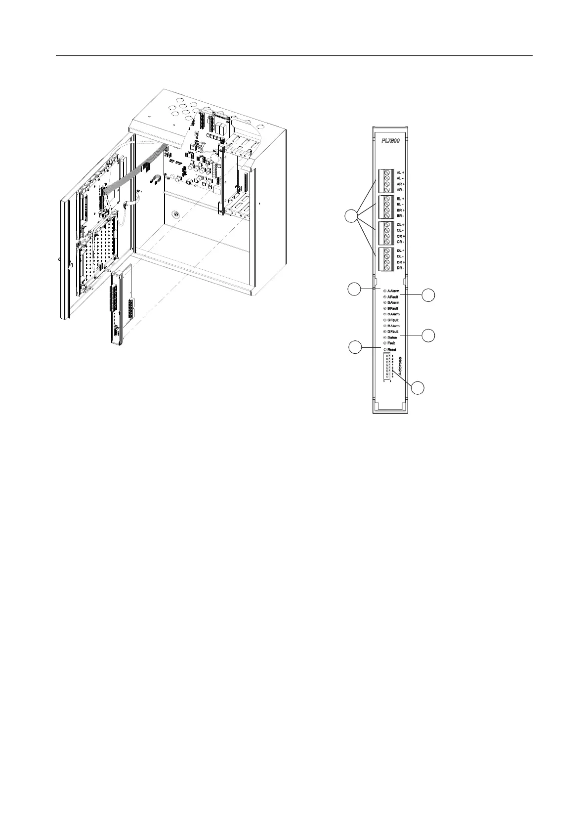
Fig. 22: Slot card installation
Fig. 23: PLX800 Loop Expansion Card
1 – Loop connector plugs
2 – Loop A Alarm optical indicator (similarly for the other loops).
3 – Loop A Fault optical indicator (similarly for the other loops)
4 – Status indicator
5 – Reset switch
6 – Addressing DIP switch
1
2
3
5
6
4
 Loading...