FIRECLASS Fire detection system PLX800 Loop Expansion Card Details
Installation Guide Doc. version 2.0 31
12.1 PLX800 Loop Expansion Card Details
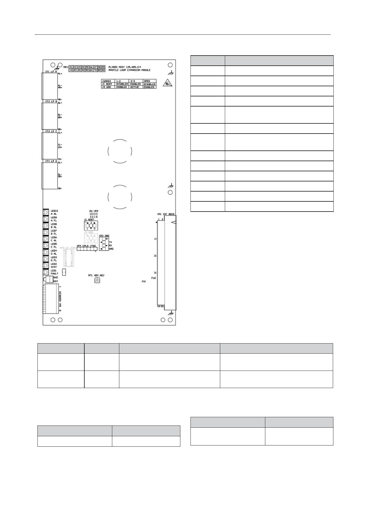
Fig. 25: PLX800 - Jumper, switch and terminal Positions
Item Function
J1 Boot Mode jumper
J2 Watchdog Options jumper
SW1 DIP switch (Internal N-BUS address)
SW2 Reset button
XP1 Slot backplane (Internal NBUS) connec-
tor
XP2 Debug Port (RS232) connector
XP3 Auxiliary JTAG port for Loop micropro-
cessor
XP4 Auxiliary JTAG port for CPLD
RT1 Rheostat for loop 40V adjustment
XT1 Loop A connector
XT2 Loop B connector
XT3 Loop C connector
XT4 Loop D connector
Table 14: PLX800 Jumper, Connector and Switch Functions
Jumper 1-2 2-3 OPEN
J1Boot Mode Disabled * Enabled (use this when updating firm-
ware)
Disabled
J2Watchdog Enabled * Active (microprocessor in reset) Disabled (use this setting when updating
firmware)
Table 15: PLX800 - Jumpers setting
* Default
State Condition
Fixed On Microprocessor failed
Table 16: PLX800 Microprocessor Status Optical Indicator
Blinking On/Off
0.5 seconds/0.5 seconds
Normal function
State Condition
Table 16: PLX800 Microprocessor Status Optical Indicator
 Loading...