VYPER
™
VARIABLE SPEED DRIVE
OPERATION
S100-200 IOM (MAY 08)
Page 44
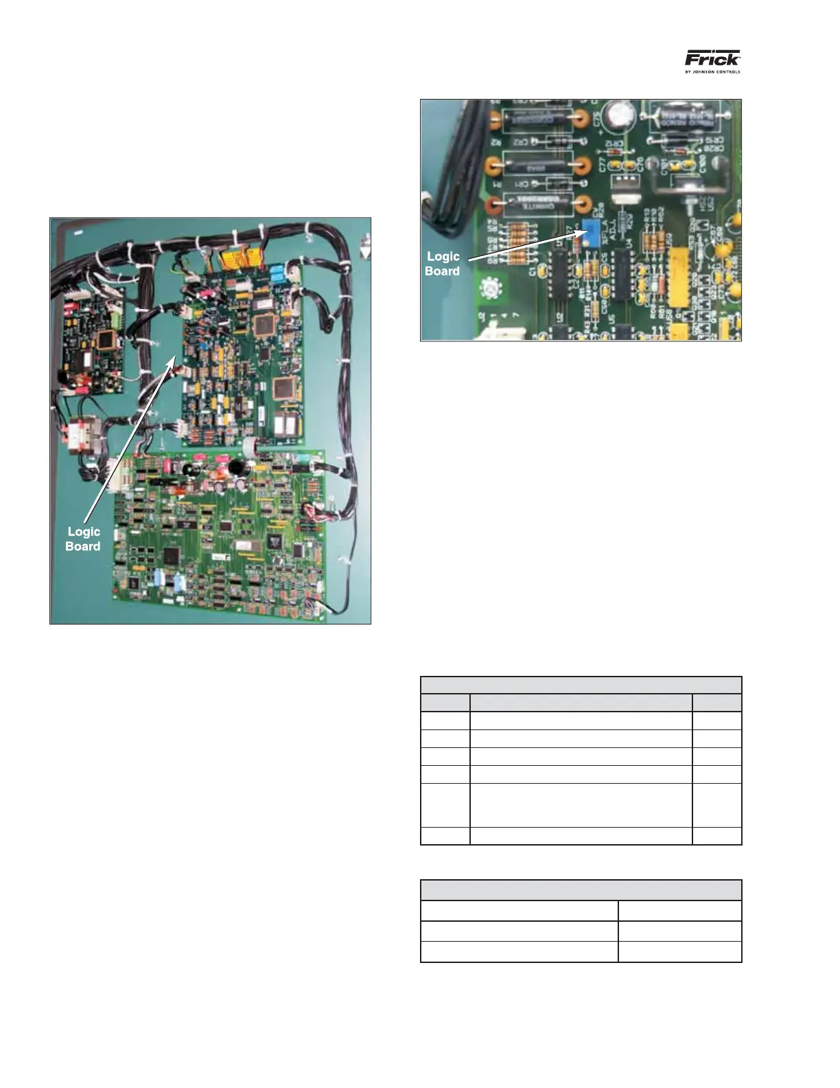
Figure 52 - Location of Trim Pot on Logic Board
Once the trim pot is located, the calibration can be viewed
by performing the steps shown on the next page on the
Quantum
™
LX panel screen.
Access the Vyper
™
Level 2 screen, described previously, as
shown in Figure 53.
The trim pot on the Vyper
™
Logic board must be adjusted to
represent the Job FLA based on the guidelines in Table C.
With a small, fl at screw driver, rotate the trim pot control until
the desired Job FLA setting is achieved. The Quantum
™
LX
screen will provide feedback to the operator as the adjust-
ment is made. Close the Vyper
™
cabinet and secure with
the door latches.
Once the Job FLA is set the installation of the drive should
be complete.
NOTE: If Logic Board is replaced, the Job FLA must be
reset to the proper value using the Job FLA Trim Pot.
Tables C and D: Job FLA Calculation
Table C: Limit Calculations
Line Parameter Value
1 “Applied Motor FLA” *
2 Motor Service Factor 1.15
3 Multiply Line 1 x Line 2
4 HP Rating of Vyper Drive
5
Vyper Amp Limit
If Line 4 is 305 / 254 HP, Value is 380 A
If Line 4 is 437 / 362 HP, Value is 565 A
6 Multiply Line 5 x 1.05
* See SETTING THE MOTOR SCREEN section
Table D: Job FLA Calculation
If in Table C Job FLA
Line 3 is Less than Line 6 = Line 3
Line 3 is greater than Line 6 = Line 5
Adjust the trim pot on the Vyper
™
Logic board until the Job
FLA is identical to the value calculated in Table D.
SETTING THE JOB FLA
The fi nal item for setup of the Vyper
™
is adjusting the Job
FLA via trim pot on the Vyper
™
Logic board. The trim pot sets
a value for the Job Full Load Amps (FLA). The adjustment
is performed at two locations; the fi rst is the trim pot on the
logic board mounted on the right door of the Vyper
™
cabinet.
See Figure 51.
Figure 51 - Logic Board Inside Right Cabinet Door
The trim pot is located on the Vyper
™
Logic board which is
mounted in the center of the right cabinet door. See Figure
49. The trim potentiometer ( trim pot) is a small blue rectan-
gular component located on the left side of the Vyper
™
Logic
board. See Figure 52. The trim pot can be adjusted by a small
straight screw driver.
 Loading...

