Johnson Controls
Start-Up & Operation Guide | 5586996-JSG-A-0120
19
Start-Up
The control circuit is tested in the factory to ensure that
all of these steps are followed. The gas heat circuit is
tested in the factory with natural gas to ensure proper
operation of the unit.
Post Start Checks
When a signal is received at the gas heat control mod-
ule from the unit controller, verify:
• Combustion blower starts and runs for 30 sec-
onds before the spark is initiated
• Spark igniter sparks
• Gas valve opens
• Burners light from left to right in a 2.5 second time
frame in sequential order, as well as establish a
stable ame immediately upon ignition
• There are no gas leaks in the unit piping and the
supply piping
• Correct manifold gas pressures in accordance
with Manifold Staged Gas Pressure Adjustment
on page 19
• Supply pressure
• Supply pressure must be within the limita-
tions shown in Table 9.
• Supply pressure should be checked with all
gas appliances in the building at full fire.
• At no time should the standby gas pressure
exceed 10.5 iwg, nor the operating pressure
drop below 4.5 iwg for natural gas; or the
standby gas pressure exceed 13.0 iwg, nor
the operating pressure drop below 11.0 iwg
for propane. When the gas pressure is out-
side these limits, contact the installing me-
chanical contractor for corrective action.
• The ame is stable, with ame present only at the
end of the burner, no burning is occurring inside
the burner. There should be little yellow tipping of
the ame.
• There may be some smoke through the ue, due to
tooling oil burning off of the heat exchanger tubing.
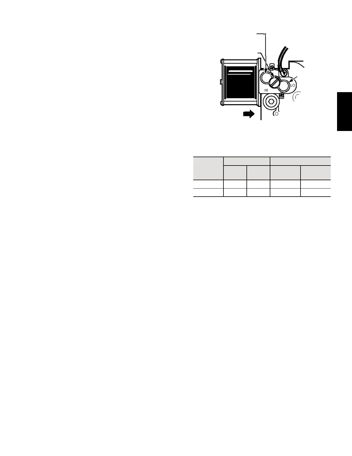
Manifold Staged Gas Pressure Adjustment
Small adjustments to the manifold gas pressure can be
made by following the procedure outlined below. Refer
to Figure 2 for the high and low fire pressure regulator
adjustment locations.
REGULATOR
LOW FIRE
PRESSURE
REGULATOR
TWO STAGE
PRESSURE
REGULATOR
REGULATOR VENT COVER
LD11760A
Figure 2: Manifold Gas Pressure Adjustment
Table 9: Staged Gas Low Fire/High Fire Pressures
Type of
Gas
Line Pressure
Manifold Pressure
Min Max
Low Fire
+/- 0.3 iwg
High Fire
+/- 0.3 iwg
Natural 4.5 iwg 10.5 iwg 1.2 iwg 3.5 iwg
Propane 11.0 iwg 13.0 iwg 3.5 iwg 10.0 iwg
1. Turn OFF the gas to the unit.
2. Use a 3/16 inch Allen wrench to remove the 1/8
inch NPT plug from the outlet pressure tap of the
manifold.
3. Install a brass adapter to allow the connection
of a hose to the outlet pressure tap of the valve.
4. Connect the hose to a manometer capable of
reading the required manifold pressure value.
5. Turn ON the gas to the unit.
6. Adjust the high re manifold pressure:
a. Place the heat section into high fire operation.
b. Compare high fire manifold pressure to Table
9.
c. Remove the cap from the high fire pressure
regulator.
d. Use a 3/32 Allen wrench to make the mani-
fold pressure adjustment. Increase manifold
pressure by turning the screw clockwise;
decrease manifold pressure by turning the
screw counterclockwise.
e. Place a finger over the adjustment opening
while verifying the manifold pressure.