Electrical data
Table 5: Electrical data
Model
(capacity)
Power supply
ELB/RCD rated
current (A)
*
ELB/RCD fault
current (mA)
*
Power source
cable size
Low-voltage
cable size
Circuit
breaker (A)
HMH72B24
208/230 V~ /60
Hz
25 30 3 x 12 AWG 5 x 16 AWG 25
HMH72B36
208/230 V~ /60
Hz
35 30 3 x 10 AWG 5 x 16 AWG 35
HMH72B48,
HMH72B60
208/230 V~ /60
Hz
50 30 3 x 8 AWG 5 x 16 AWG 50
*
where required by code
Note: Maximum running current (A): refer to the
nameplate.
Note:
• Follow local codes and regulations when
selecting field wires and ensure all wires are
the minimum wire size.
• When the low-voltage cable is longer than 262
ft (80 m), select a larger wire size.
• Install a main switch and an ELB/RCD for each
system separately. Select a high-response ELB/
RCD that acts within 0.1 s.
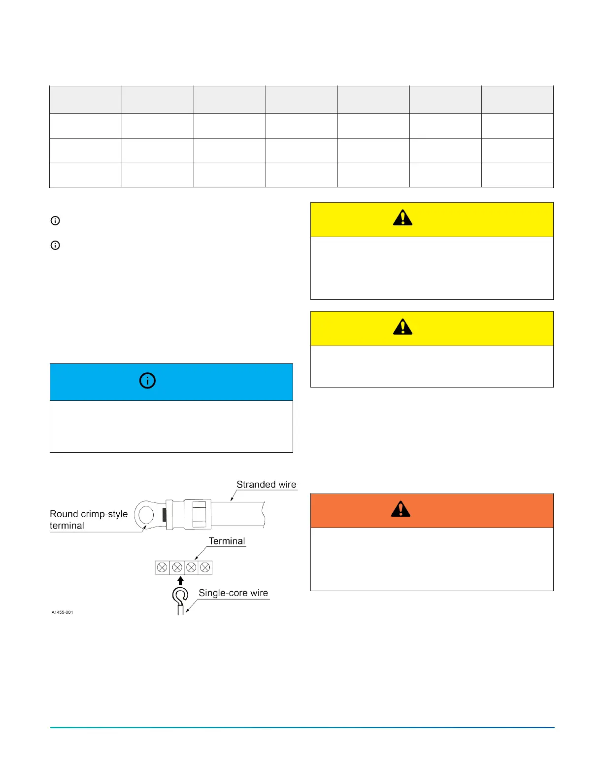
NOTICE
When connecting to the terminal block using a
stranded wire, make sure to use the round crimp-style
solderless terminal.
Figure 19: Connecting the power supply
Performing a test run
About this task:
Perform a test run after the refrigerant piping, drain, and
wiring are finished.
CAUTION
The outdoor section is provided with a compressor
and base heater. Check to ensure the main power has
been on for more than 6 h ahead of unit operation to
avoid damage to the compressor.
CAUTION
Do not operate the system until all the checks have
been performed.
1. Check to ensure that the service base valves of the
outdoor unit are fully open.
2. Check to ensure that the electric wires are fully
connected.
3. Use the thermostat to turn on the system and then
proceed with the test run.
4. Turn off the power after the test run is finished.
WARNING
Do not touch any of the parts at the discharge gas
side by hand. The compressor chamber and the pipes
at the discharge side are heated to temperatures
higher than 194°F (90°C).
Installation Manual: HMH7 Series - 17 SEER Horizontal Discharge Modulating Heat Pump 17
Johnson Controls Ducted Systems

 Loading...


