5566217-JIM-C-1019
Johnson Controls Ducted Systems 37
also require various minimum clearances to allow for adequate
internal cooling of the drive during operation.
The unit comes with a mounting bracket installed in the blower
access compartment which may accommodate other vendor's
drives depending on their size. In order to use the unit's
mounting bracket, the maximum recommended drive
dimensions are limited to approximately 9 in. H x 5 in. W x
7.5 in. D.
If the drive does not fit in the allotted space, then it must be
mounted elsewhere. It can be mounted in one of the following
locations.
• Within the building on a perpendicular wall that is not
subjected to excessive temperature, vibration, humidity,
dust, corrosive gas, or explosive gas.
• Within an appropriate enclosure rated for outside
installation to safeguard against moisture, dust, and
excessive heat.
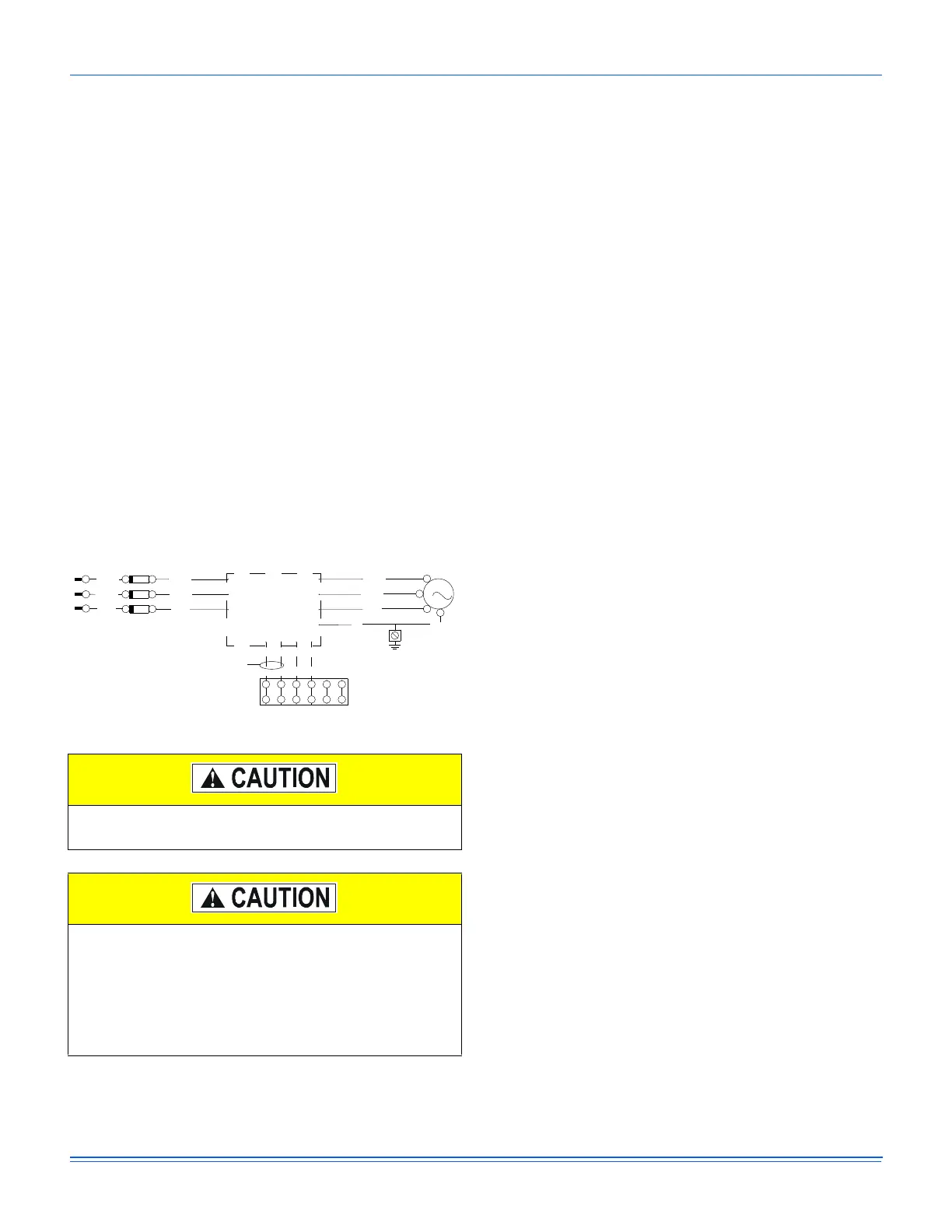
The power leads to the drive (L1, L2, L3) and from the motor
(T1, T2, T3) are temporarily spliced together with wire nuts.
After you remove the wire nuts, connect the wires to the field-
installed VFD according to the VFD wiring diagram (See Figure
27). The VFD must also be grounded according to the
manufacturer's specifications.
Figure 27: Simplified VFD wiring
A terminal block located in the control box is provided for field
connection of the VFD speed reference signal (2-10 VDC) and
to the normally-open, run-permit auxiliary contact. The use of
shielded cable is recommended for the above control wiring
connections. For VFD-ready units also equipped with gas/
electric heat, a terminal block located in the unit's control box
and connected to the VAV board's VAV BOX terminal, must be
field wired to the building's VAV boxes to ensure fully open
dampers during heating operation.
Optional hot gas bypass (HGBP)
To allow for low cooling load operation, a direct-acting,
pressure-modulating bypass control valve installed on the
system #1 discharge line is used to divert high temperature,
high pressure refrigerant around the TXV in order to maintain a
desired minimum evaporator pressure.
The opening pressure of the bypass valve is adjustable
between 95 and 115 psig with a factory-setting of 105 psig.
HGBP is standard on all units with VAV and optional with CV
units.
Economizer sequences
Several functions can drive the economizer, including: minimum
position, free cooling, economizer loading, and minimum
outdoor air supply.
Economizer minimum position
The economizer minimum position is set during occupied mode
when outside air is not suitable for free cooling. The position of
the damper is set proportionally between the Economizer
Minimum Position and the Economizer Minimum Position Low
Speed Fan setpoints, in relationship to the VFD output
percentage. On a constant volume single speed supply fan
system both setpoints should be set to the same value.
Free cooling
Four types of free cooling options are available: dry bulb
changeover, single enthalpy, dual enthalpy changeover, and
Auto.
Dry bulb changeover
For dry bulb economizer operation, the outside air is suitable for
free cooling if the outside air temperature is 1°F below the
Economizer OAT Enable setpoint and 1°F below the Return Air
Temperature.
Free cooling is no longer available if the outside air temperature
rises above either the Economizer OAT Enable setpoint or the
return air temperature.
Single enthalpy changeover
For single enthalpy economizer operation, the outside air is
suitable for free cooling if the outside air enthalpy is at least 1
BTU/lb below the Economizer Outside Air Enthalpy setpoint
and the outside air temperature is no greater than the RAT plus
9°F.
If the outside air temperature rises above the RAT plus 10°F,
free cooling is no longer available. The outside air temperature
must drop to no greater than RAT plus 9°F to enter free cooling
again.
Do not connect AC power to the T1, T2, T3 drive
terminals to prevent damage to the VFD.
The fuses (FU3, FU4, FU5) supplied with the unit are
sized according to the electrical load of the blower
motor, but may not provide adequate protection to the
customer-installed drive, depending on its
specifications. When you select and install a drive, refer
to the drive manufacturer's recommendations for proper
fuse sizing.
ELEMENTARY DIAGRAM
VFD
TB8 (IN CONTROL BOX)
RUN PERMIT
(DIGITAL)
SPEED REF
(ANALOG)
(2-10 VDC)
GND
GRN
GND
GRN
GND
1 DMTR
118 / BK
119 / BR
120 / Y
3
M
(T1)
(T2)
(T3)
( )
(L1)
(L3)
(L2)
722 / BK
725 / BR
728 / Y
720 / PR
723 / BR
726 / O
TB1
FU3
FU5
FU4
12345
6
L3
L2
L1
T1
T2
T3
 Loading...