6139716-UIM-A-0422
Johnson Controls Ducted Systems 3
Inspection
Upon receiving the air handler, inspect for possible damage during tran-
sit. If damage is evident, note the extent of the damage on the carrier’s
freight bill. A separate request for inspection by the carrier’s agent must
be made in writing. Consult the local distributor for more information.
Before installation, check the unit for screws or bolts loosened in transit.
There are no internal shipping or spacer brackets that need removing.
You must verify that all accessories, such as heater kits and coils, are
available. Complete installation of these accessories or field conversion
of the unit before setting the unit in place or connecting any wiring,
ductwork, or piping.
Section III: Unit installation
Unit sizing
• The size of the unit must be based on an acceptable heat loss or
gain calculation for the structure. Use Air Conditioning Contrac-
tors of America (ACCA) Manual J or another approved method.
• Only connect the air handler to a duct system that has an external
static pressure within the allowable range.
• Airflow must be within the minimum and maximum limits
approved for electric heat, indoor coils, and outdoor units.
• When an air handler is installed so that supply ducts carry air cir-
culated by the air handler to areas outside the space containing
the air handler, the return air is also handled by one or more ducts
sealed to the air handler casing and terminating in the space to
be cooled or heated.
• Refer to the unit rating plate for the air handler model number and
then see the dimensions page of this manual for supply air ple-
num dimensions. The plenum must be installed according to the
instructions.
• The installer must check available supply power and verify that it
is within the normal operating voltage range for the unit. The
acceptable voltage range for these units is as follows:
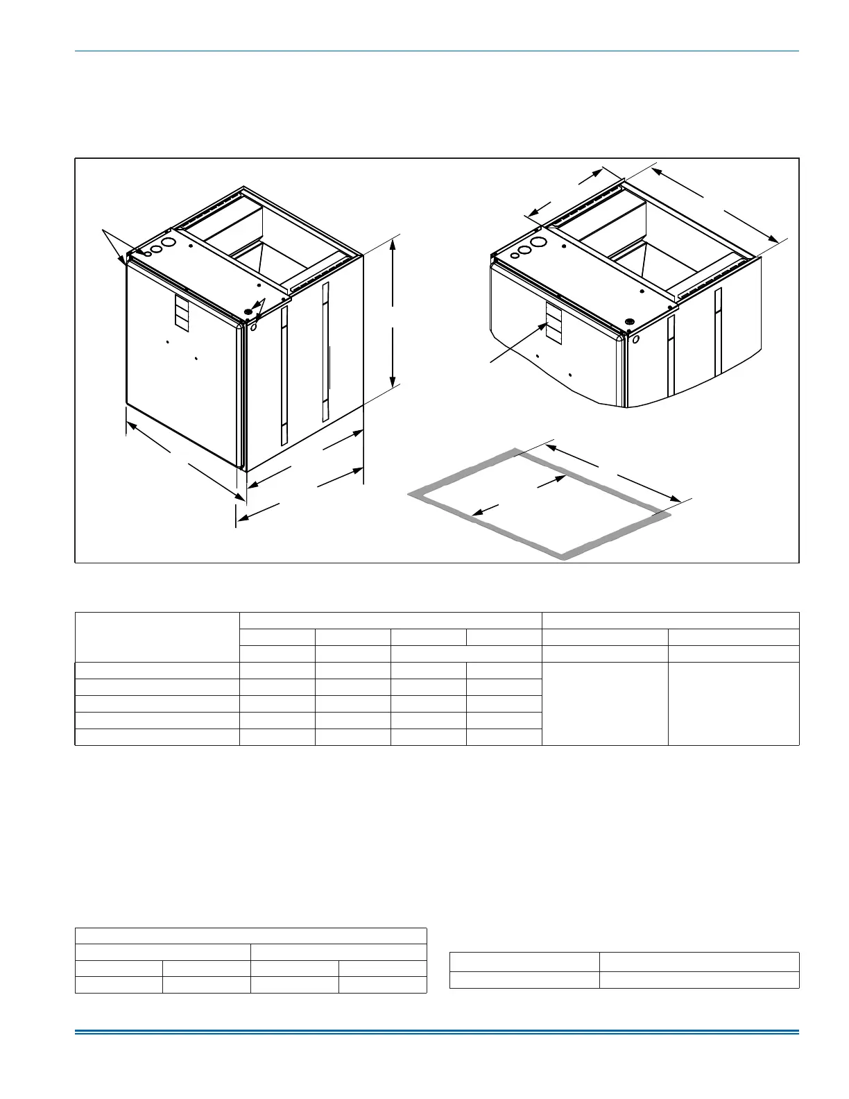
Figure 2: Dimensions and duct connection dimensions
Table 1: Dimensions
1
1. All dimensions are in inches.
Models
Dimensions
Wiring knockouts
2
2. Actual size (conduit size).
A B C D E F
Height (in.) Width (in.) Opening widths (in.) Power (in.) Control (in.)
JMET08BS2N1 22 3/4 17 1/2 16 1/2 16 1/2
7/8 (1/2)
1 3/8 (1)
1 23/32 (1 1/4)
7/8 (1/2)
JMET12BS2N1 22 3/4 17 1/2 16 1/2 16 1/2
JMET12CS2N1 22 3/4 21 20 20
JMET16CS2N1 22 3/4 21 20 20
JMET18DS2N1 22 3/4 24 1/2 23 1/2 23 1/2
A1712-001
B
20 1/2 in.
21 1/2 in.
F
A
D
12 3/16 in.
19 1/8 in.
C
E
Bottom inlet
dimensions
Service
disconnect panel
Top outlet
dimensions
Entering air temperature limits
Wet bulb temperature (°F) Dry bulb temperature (°F)
Minimum Maximum Minimum Maximum
57 72 65 95
Air handler voltage
Normal operating
1
voltage range
1. Rated in accordance with ARI Standard 110, utilization range A.
208/230-1-60 187 V to 253 V