6139716-UIM-A-0422
4 Johnson Controls Ducted Systems
Clearances
It is essential to provide the following clearances:
• Maintenance and servicing access - minimum 36 in. from the
front of the unit for blower motor
• The supply air ductwork connected to this unit is designed for 1
in. clearance for the first 18 in. of duct length to combustible
materials.
• A combustible floor base accessory is available for downflow
applications of this unit, if required by local code.
Location
Location is usually predetermined. Check with the owner’s or dealer’s
installation plans. If location has not been decided, consider the follow-
ing in choosing a suitable location:
• Select a location with adequate structural support, space for ser-
vice access, and clearance for air return and supply duct connec-
tions.
• Normal operating sound levels may be objectionable if the air
handler is placed directly over some rooms such as bedrooms or
a study.
• When installing an indoor coil in an attic or above a finished ceil-
ing, an auxiliary drain pan must be provided under the air handler
as is specified by most local building codes.
• A sufficient electrical supply must be available.
• If locating the unit in an area of high humidity, such as an uncon-
ditioned garage or attic, nuisance sweating of the casing may
occur. On these installations, completely seal the unit duct con-
nections and other openings, and use a wrap of 2 in. fiberglass
insulation with vinyl vapor barrier.
Air handler configuration
These air handler units are ready to install in any position shown in Fig-
ure 3. Some XAH model coils require a section of duct between the
indoor coil and the modular air handler. See Horizontal right applica-
tions.
Horizontal right applications
An pan extension to reduce the risk of condensate blow-off is provided
with certain models of XAH indoor coils. It is essential to construct, insu-
late, and attach a 6 in. length duct extension between the XAH coil cas-
ing and the modular air handler casing to allow enough room to install
the pan extension. The suggested method is as follows:
Note: This method consists of two identical field fabricated duct sec-
tions.
1. Attach one duct section to the leaving air end of the XAH indoor
coil.
2. Attach the other duct section to the entering air end of the modular
air handler.
3. Attach the two sections together using s-lock and drive cleats. See
Figure 5.
Note: A = modular air handler width (see column B in Table 1)
Air handler and coil upflow, downflow, and horizontal posi-
tions where not using a pan extension
1. Apply the neoprene gasket to the return air end of the air handler.
2. Attach three tie plates to the external sides and back of the air
handler casing using screws. See Figure 4.
3. Position the air handler casing over the appropriate coil opening
(depending on configuration). See Figure 3.
4. Attach the three tie plates to the coil casing using screws. See Fig-
ure 4.
5. Remove the coil access panel.
6. Slide the coil out of the coil cabinet and set the coil to the side.
7. Locate the 2 in. wide foam gasket.
8. Apply the foam gasket over the air handler and coil mating seams
on the interior of both unit sides and back.
9. Slide the coil into the housing and install the coil access panel and
coil filter door.
Figure 3: Typical installation
Figure 4: Coil and air handler attachment details
A1711-001
Upflow Downflow Horizontal right
Horizontal left
A1757-001
Outer tie plate (three places)
Blower
Coil
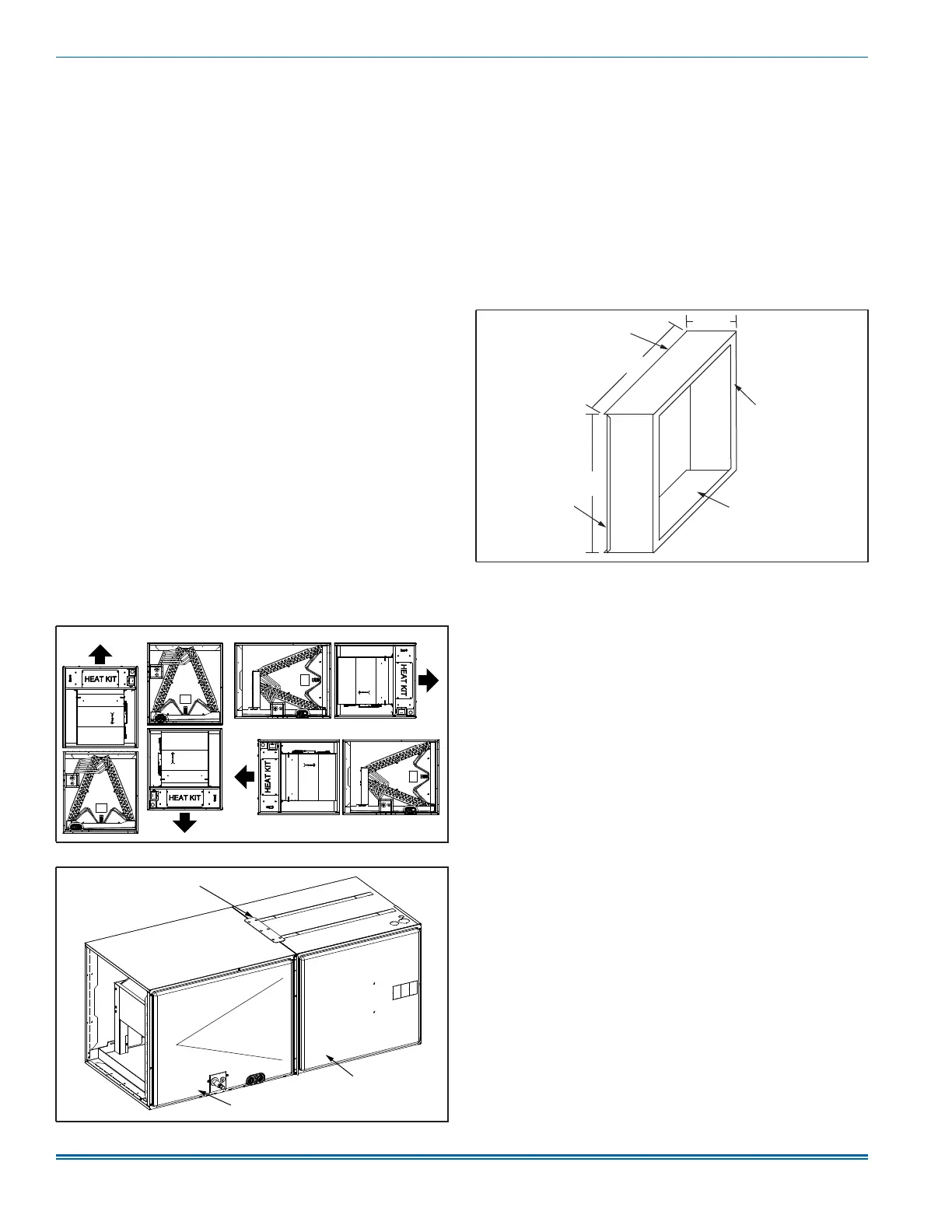
Figure 5: Duct section - modular air handler - horizontal right
A
A1762-001
3.5 in.
1 in. flange in
1 in. duct liner
S-lock
Drive cleat
20.5 in.