6139716-UIM-A-0422
Johnson Controls Ducted Systems 7
Section VI: Line power connections
Power can be brought into the unit through the supply air end of the unit
(top left when unit is vertical) or the left side panel. Use the hole appro-
priate to the unit’s orientation in each installation to bring the conduit
from the disconnect.
The power lead conduit must be terminated at the electrical control box.
See Table 10 to Table 13 and the latest edition of the National Electric
Code, or in Canada the Canadian electrical Code, and local codes to
determine correct wire sizing.
To minimize air leakage, seal the wiring entry point on the outside of the
unit.
All electrical connections to air handlers must be made with copper con-
ductors. Direct connection of aluminum wiring to air handlers is
not approved.
If aluminum conductors are present, all applicable local and national
codes must be followed when converting from aluminum to copper con-
ductors prior to connection to the air handler.
The chosen conductor and connections must all meet or exceed the
amperage rating of the overcurrent protector (service disconnect or
fuse) in the circuit.
Existing aluminum wire within the structure must be sized correctly for
the application according to the National Electric Code and local codes.
Use caution when sizing aluminum rather than copper conductors, as
aluminum conductors are rated for less current than copper conductors
of the same size.
Section VII: Low voltage control
connections
The 24 V power supply is provided by an internally wired low voltage
transformer that is standard on all models. If connecting the unit to a
208 V power supply, the low voltage transformer must be rewired to the
208 V tap. See the Wiring diagram.
Field supplied low voltage wiring can exit the unit through the top right
(when unit is vertical upflow) or the right side panel. See Figure 2.
Remove the knockout and pierce the foil faced insulation to allow wiring
to pass through.
Use as small of a hole as possible to minimize air leakage. Install a 7/8
in. plastic bushing in the selected hole and keep low voltage wiring as
short as possible inside the control box.
To further minimize air leakage, seal the wiring entry point at the outside
of the unit. Connect the field wiring at the pigtails supplied with the air
handler. See Figure 14 to Figure 22 for system wiring.
Section VIII: Blower speed connections
Adjust the blower motor speed to provide airflow within the minimum
and maximum limits approved for indoor coils, electric heat, and out-
door units. Make speed tap adjustments at the motor terminal block.
See Table 14 for airflow data. Connect the motor wires to the motor
speed tap receptacle for the speed required.
WARNING
Before obtaining access to terminals, all supply circuits must be dis-
connected.
WARNING
A fused disconnect switch must be field provided for the unit to be in
compliance with UL 60335-2-40 Clause 7.12.2.
!
!
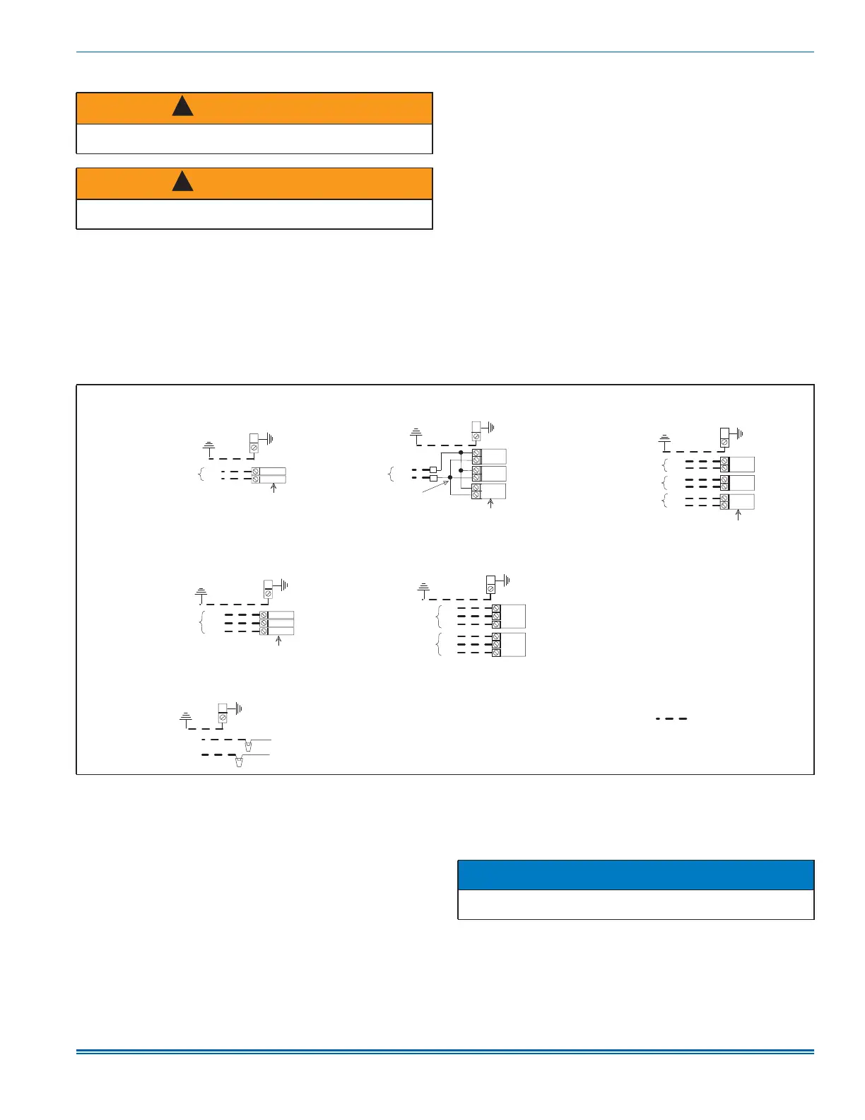
Figure 11: Line power connections
.
A1699-001
3
2
1
GND
SD
SD
SD
GND
GND
CKT
L1
L2
L1
L2
SD
SD
SD
CKT
CKT
2
1
L1
L2
L3
L1
L2
L3
L1
L2
L3
GND
CN
CN
CKT
CKT
SD
SD
GND
GND
L1
L2
L1
L2
L1
L2
Two circuits on 15 kW to 20 kW
Three circuits on 25 kW
Field power wiring
(208/230 V)
Component Codes:
GND - Ground lug
SD - Service disconnect
CKT - Circuit
CN - Wire connector/nut
1 Phase Electric Heat Power Options:
3 Phase Electric Heat Power Options:
Single source power
Power supply Power supply Power supply
Terminal block or service disconnect
Jumper bar
Two circuits on 15 kW to 20 kW
Three circuits on 25 kW
Multi-source power with jumper bar Multi-source power
No Electric Heat:
Power supply
Single source power Multi-source power
Power supply
Terminal block or service disconnect
Power supply
NOTICE
All wiring must comply with local and national electrical code require-
ments. Read and heed all unit caution labels.