4 M9216 Series Electric Spring Return Actuators Installation Instructions
8. Remove the manual crank, and return it to its
original position on the actuator cover.
Notes: When changing the rotation range on the
xGC models with auxiliary switches, one or
both switches may need to be adjusted. See the
Auxiliary Switches (xGC Models) section.
When changing the rotation range on HGx models with
zero and span potentiometers, both potentiometers
must be adjusted. See the Potentiometers
(HGx Models) section.
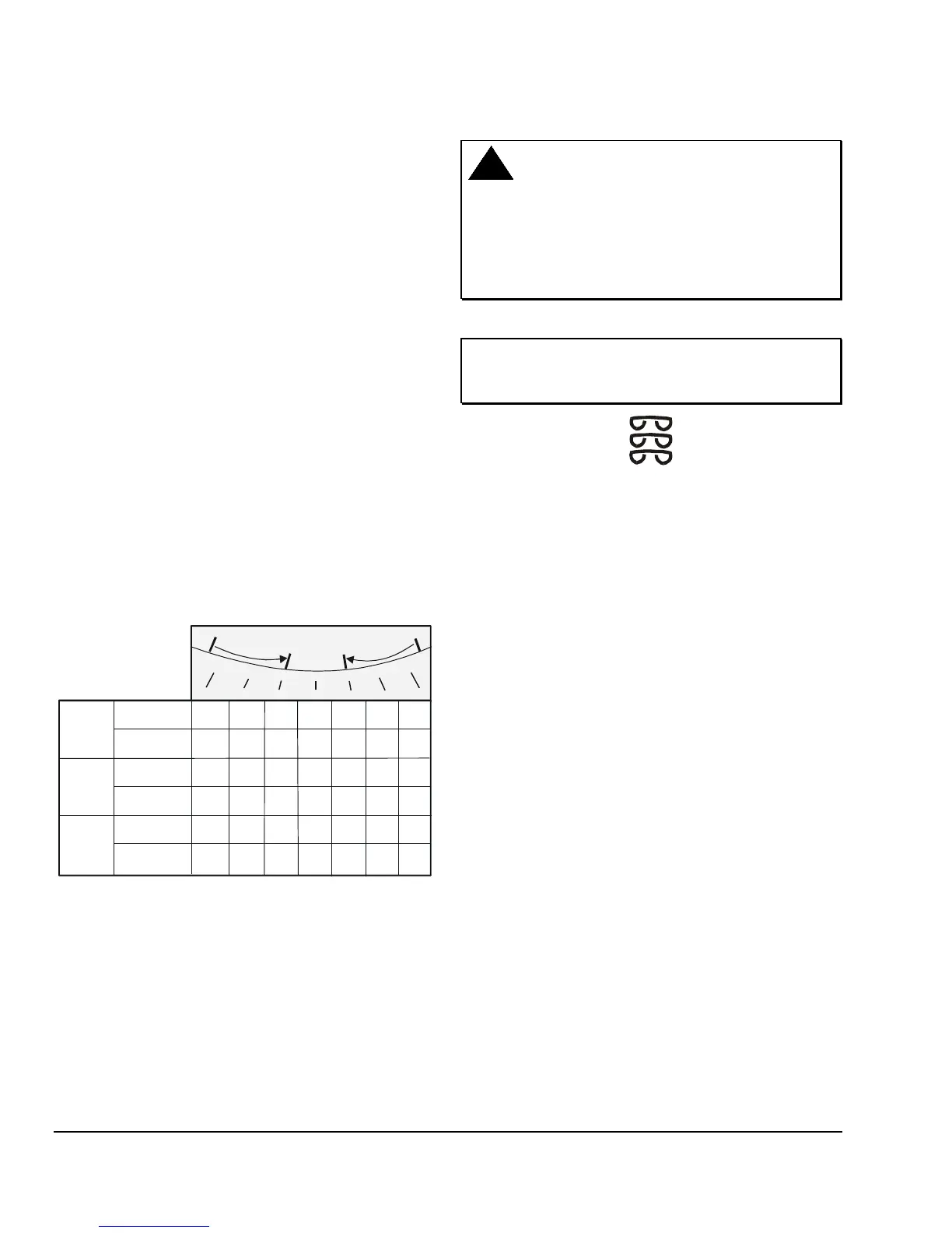
Feedback Signal
The feedback signal varies with a change to the
rotation range. The resistance feedback is reduced
corresponding to the reduced rotation range for the
AGD and AGE models. For the HGx and JGx models,
a change to the rotation range changes the feedback
signal and the operating range. This applies to the
GGx models only in the fixed mode. (See Figure 6.)
Note: Refer to the Setup and Adjustments, Fixed or
Auto Mode (GGx Models) section for the GGA and
GGC models. Once calibrated, a change to the rotation
range does not affect the feedback signal and
operating range of the GGx models.
90°
90°
0.0 V
2.0 V
10.0 V
8.7 V
7.3V
6.0 V
4.7 V
3.3 V
10.0 V
8.3 V
6.7 V
5.0 V
3.3 V
1.7 V
75°
75°
60°
60°
45°
45°
30°
30°
15°
15°
0°
0°
Rotation Range
2-10V
Feedback
0-10V
Feedback
Direct
Acting
1000Ω
135 Ω
113
Ω
667 Ω
90
Ω
45
Ω
167Ω
(Ω is ohms.)
Ω
Ω
0
0
833
Ω
68
Ω
23
Ω
0-135 ohms
Feedback
0-1000 ohms
Feedback
Ω500
333 Ω
Direct or
Reverse
Acting
2-10 V
Feedback
Reverse
Acting
0-10V
Feedback
0.0 V 1.7 V
3.3 V
5.0 V 6.7 V
8.3 V
10.0 V
10.0 V8.7 V
7.3 V
6.0 V
4.7 V
3.3 V
2.0 V
Rotation Limiter
Adjustment
Rotation Limiter
Adjustment
Note:
0-135 ohms feedback is available on AGD models and
0 to 1000 ohms feedback on AGE models. .
0-10 V or 2-10 V is available on GGx, HGx, and JGx models.
Figure 6: Nominal Feedback Signal Relative to the
Rotation Range
Wiring
CAUTION: Equipment Damage Hazard.
Disconnect all power supplies before wiring
connections are made, or prior to performing
maintenance. Check all wiring connections before
applying power to the system. Short-circuited or
improperly connected wires will result in permanent
damage to the equipment.
IMPORTANT: Install all quick-connect terminals in
the same direction to prevent shorting. (See Figure
7.)
Figure 7: Orientation of Terminals
Observe the following when wiring an M9216 actuator:
• Make all wiring connections in accordance with the
National Electrical Code and local regulations.
• Note that there is a 25-second delay for all models
(except the BGx and GGx), before the actuator
responds after power is applied.
• Do not switch 24 VAC from CW to CCW
(or CCW to CW) on the AGx models in less than
0.5 seconds.