M9216 Series Electric Spring Return Actuators Installation Instructions 5
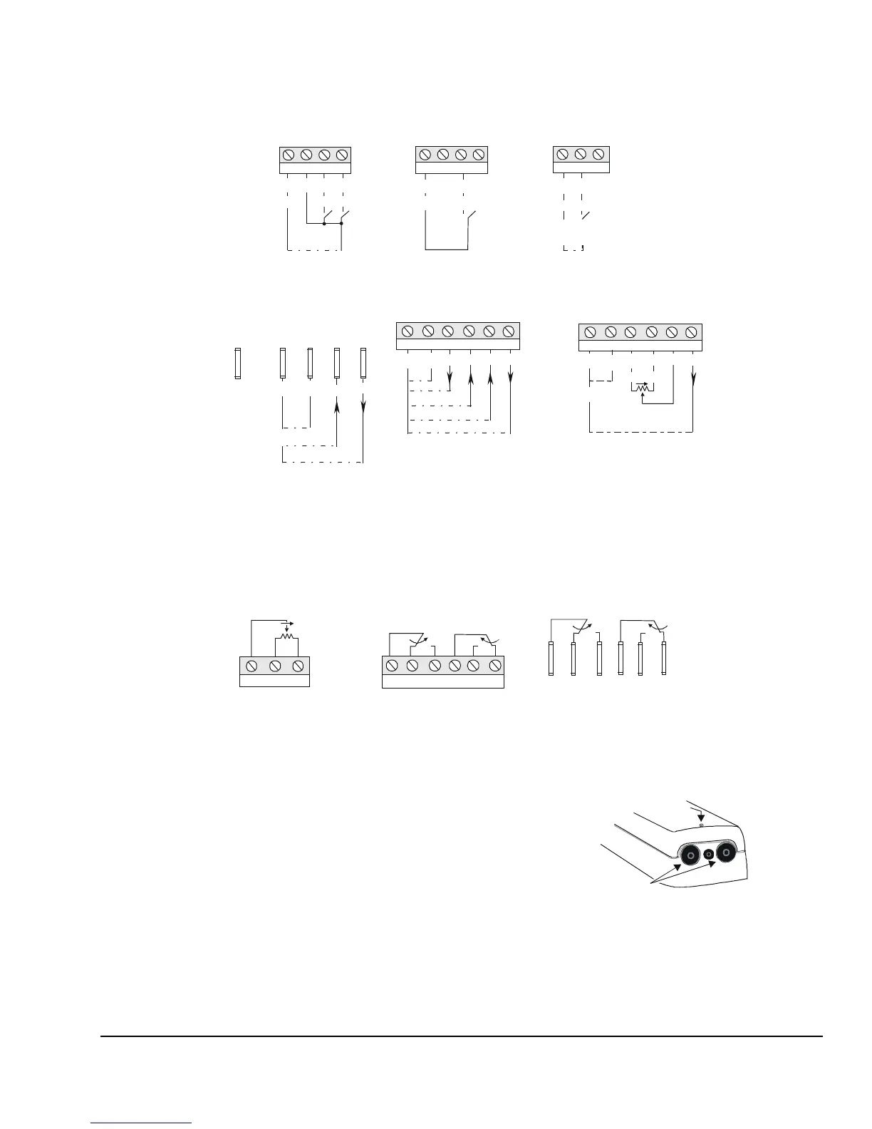
Refer to Figure 8 for the applicable M9216 actuator.
Terminal Block 1
Terminal Block 2
NC
NO
NO
NC
21 22 23 24 25 26
Switch S1
10°
Switch S2
80°
Auxiliary Switches
(Shown Factory Set)
Models: AGC, BGC,
HGC, and JGC
* CW rotation for the On/Off models when the coupler is inserted in the front of the
actuator, but CCW rotation when it is inserted in the back of the actuator.
Models: AGD = 0 to 135 ohms
AGE = 0 to 1000 ohms
CW
0% 100%
11 12 13
Feedback
Potentiometer
24 VAC
24 VDC
CW CCW
COM
Floating Control
Models: AGA, AGC, AGD, and AGE
On/Off Control
24 VAC
24 VDC
1 2 3 4
1 2 3 4
CW
*
^
-
~
+
~
+
~
+
~
+
^
-
COM
1 2 3
On/Off Control
Models: BGA and BGC
*
24 VAC
24 VDC
~
+
^
-
COM CW
0-20 mA
0-10 V
0-10 V
Proportional Control
Models: HGA and HGC
24 V
+ +
+
+
^
-
1 2 3 4 5 6
1 = Common
2 = Power
3 = Calibration Out
(for HGA and HGC
models only)
4 = Current Input
5 = Voltage Input
6 = Feedback Output
~
+
NC
NO
NO
NC
Switch S1
10°
Switch S2
80°
Auxiliary Switches
(Shown Factory Set)
Models: GGC
Note: NC is normally closed, NO is
normally open, and C is common.
C1 NC1 NO1 C2 NO2 NC2
^
-
0-10 V
Proportional Control
Models: GGA and GGC
24 V
+
+
COM
(Extra)
COM
VAC/
VDC
VDC/
mA
FB
Note: COM is common, and
FB is feedback.
~
+
^
-
0-10 V or 0-20 mA
Resistive Input Control
Models: JGA and JGC
1 2 3 4 5 6
COM
CCW CW
100-10 k ohms
0-10 V
24 V
Note: Terminals 3 and 4 function as
CCW and CW references when
the Resistive models are in the
DA mode, but as CW and CCW
references when these models
are in the RA mode.
+
+
+
^
-
^
-
~
+
Figure 8: Wiring Diagrams for M9216 Models
Wiring is made through the conduit openings or
through the conduit adaptor, which converts the
opening for a threaded NPT conduit fitting.
Through the Conduit Openings
Depending on the M9216 model selected, one or both
conduit openings are used. Refer to Figure 9 and
proceed as follows:
1. Loosen the cover screw with a Phillips No. 2
screwdriver, and remove the actuator cover.
2. Push the plastic plug out of the conduit opening
with fingertip.
Plugs
(Conduit Openings)
Cover
Screw
Figure 9: Location of the Conduit Openings
3. Insert the cable wires through the hole in the
conduit plug, and connect to the terminals using
the appropriate wiring diagrams in Figure 8.