D
imensions
(in mm)
90
220
A
B
140
54
110
DIN electrical cabinet
(12 or 18 modules)
240
A
B
140
42
122,5
370
125
DIN electrical cabinet
(24 or 36 modules)
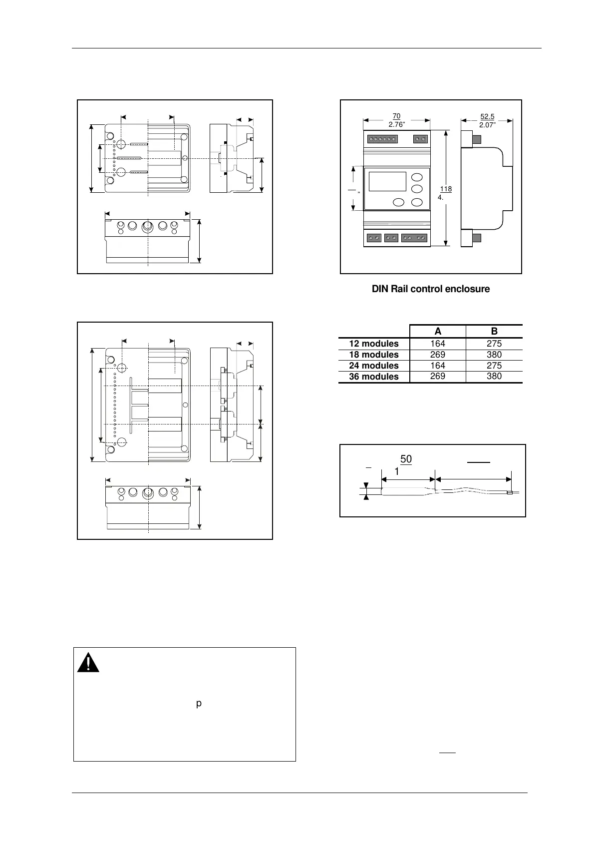
52.5
2.07”
52.5
2.07”
70
2.76”
118
4.65”
45
1.78”
DIN Rail control enclosure
AB
12 modules
164 275
18 modules
269 380
24 modules
164 275
36 modules
269 380
50
1.97”
∅
6
0.24”
2000
78.74”
A99B-9108 / A99BB-200C Sensor
W
iring Instruction
All wiring must be in accordance with local
regulations and national rules
These controllers are designed for use as an
operating control. When an operating control
failure would result in personal injury or loss of
property, it is the responsibility of the installer to
wire a separate backup control (e.g. a freeze
protection thermostat) in order not to use the
controller as an operating and safety device.
WARNING
When wiring and servicing make sure that:
•
the electric supply to the actuator is
switched off to avoid possible damage to
the equipment, personal injury or shock.
•
you do not touch or attempt to connect or
disconnect wires when electric power is on.
CR1 3
© 2010 Johnson Controls, Inc. Catalogue Section 9