Installing the NAE/NIE Technical Bulletin6
N2 Bus Ports (N2 A, N2 B) (NAE Only)
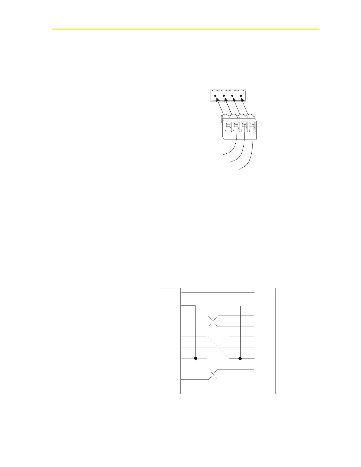
The two N2 connections on the NAE are 4-pin removable, keyed
terminal blocks (Figure 3). See the System Configuration Tool
Technical Bulletin (LIT-1201534) for more information on using the
NAE with N2 networks.
N2 REF
N2-
N2+
REF N2- N2+
SH
LD
N2Bus
+
N2
-
REF
S
NAE N2 Bus
Terminal Block
NAE N2
Terminal Block
Plug
Figure 3: N2 Terminal Block
The Shield connection (S) on the N2 ports of the NAE is not
connected to any Ground connection. S is an open terminal that can be
used as a splice connection. The N2 A and N2 B terminal blocks are
not interchangeable.
PC Serial Ports (SER A, SER B)
RS-232 ports on the NAE are used for direct connection using a
standard 9-pin female to 9-pin female, Data Terminal Equipment
(DTE) to DTE null modem cable (Figure 4):
pcserial
Shell
NAE
9-pin Female
PC Serial Port
9-pin Female
DCD
RD
TD
DTR
SG
DSR
RTS
CTS
RI
1
2
3
4
5
6
7
8
9
Shell
1
2
3
4
5
6
7
8
9
DCD
RD
TD
DTR
SG
DSR
RTS
CTS
Figure 4: 9-Pin to 9-Pin Null Modem Cable