Important: The data protection battery must
maintain a small residual charge. The battery
ships from the factory with a small residual
charge. You should connect 24 VAC power
to the network engine immediately after
connecting the battery to ensure that the
battery does not completely loose its charge,
which may damage the battery.
Note: The 24 VAC power to the network engine
charges the data protection battery. At initial
startup, the battery requires a charging period
of at least two hours before it supports data
protection if power fails. Maximum protection
(up to three consecutive power failures without
recharging time) requires a 24-hour charging
period.
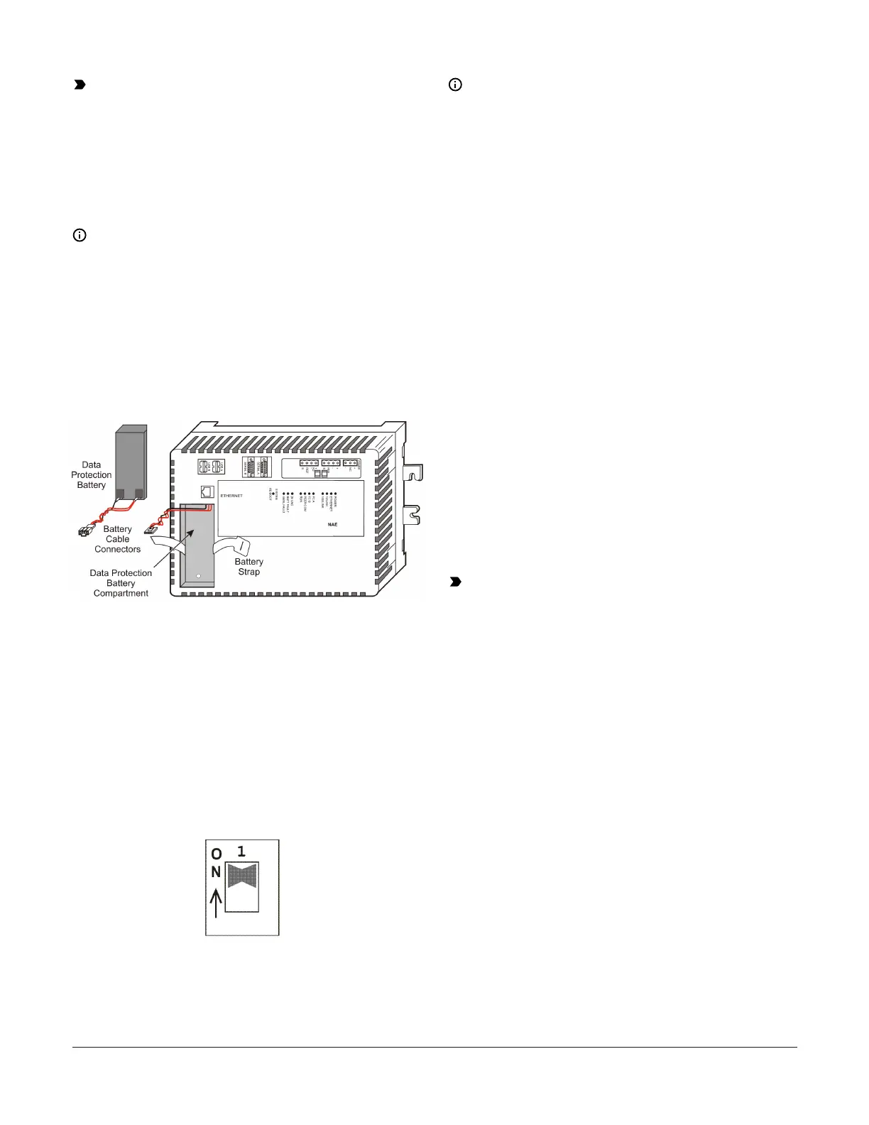
Figure 17: Network Engine data protection
battery
Setting the end-of-line switches
The network devices at each end of an FC Bus
segment must be set as network terminated devices.
The network engine has two EOL switches (one for
each FC Bus) that enable you to set the network
engine as a network terminated device on the bus.
To set a network engine as an FC Bus terminated
device, position the switch on the EOL switch block
to the ON position (Figure 18).
Figure 18: FC Bus EOL switch in the factory
default ON (up) position
Note: The EOL switches on the network engine
are factory set to ON (Figure 18). If the network
engine is not a terminated device on the FC
Bus, reposition the switch on the EOL switch
block to the Off (down) position.
Set the EOL switches appropriately for the FC A
and FC B buses. The network engine follows the
same rules as other switch-terminating devices
listed in the Setting Terminations sections of the N2
Communications Bus Technical Bulletin (LIT-636018)
and the MS/TP Communications Bus Technical Bulletin
(LIT-12011034).
Powering on the Network Engine
Apply power to the network engine by plugging
in the gray 2-pin terminal connector to the power
terminal port on the network engine (Figure 4). The
network engine requires approximately 3 minutes to
start up and become operational. See the LED test
sequence at startup section.
Startup is complete and the network engine is
operational when the (green) RUN LED is On steady
and the (red) GEN FAULT LED is Off. See Figure 19
for LED locations.
Disconnecting power from the
Network Engine
Important: The data protection battery must
be installed and charged before disconnecting
the 24 VAC supply power.
Disconnect power from the network engine by
removing the gray 2-pin terminal block from the
power terminal port on the network engine (Figure
4).
When you remove 24 VAC power from the network
engine, or supply power is lost, the network engine
is nonoperational after the power management
settings expire. The POWER LED (Figure 19) remains
On, and the data protection battery continues to
power the network engine for approximately 1 to
3 minutes so that volatile data can be backed up in
nonvolatile memory. The POWER LED goes Off when
the data backup is completed.
Troubleshooting
LED status indicators
The LEDs on the front cover of the network engine
indicate power and communication status. See
Figure 19 and Table 4.
NAE55/NIE55 Installation Guide12