Engineering manual - SAB 193-233-283 S A-frame (including ATEX)
58/168
008831 en 2020.10
Technical description
It is imperative that an uninterrupted supply of high-pressure liquid refrigerant is provided to
the injection system at all times. Two items are of extreme importance, the design of the re-
ceiver/liquid injection supply and the size of the liquid line.
It is recommended that the receiver is oversized sufficiently to retain a five minute supply of re-
frigerant for oil cooling. The evaporator supply must be secondary to this consideration. Two
methods of accomplishing this are shown below.
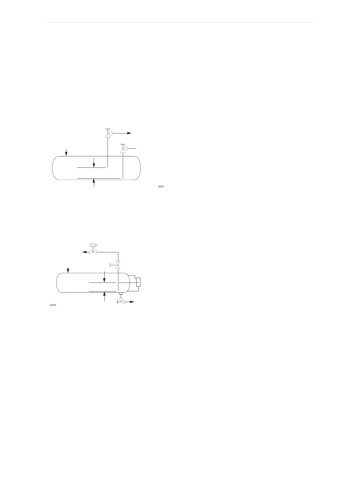
The dual dip tube method, Fig. 35, uses two dip tubes in the receiver. The liquid tube is below the
evaporator tube to ensure continued oil cooling when the receiver level is low.
Fig. 35: Dual dip tube method
The level control method, Fig. 36, uses a float level control on the receiver to close a solenoid
valve feeding the evaporator when the liquid falls below the amount necessary for five minutes of
liquid injection oil cooling.
Fig. 36: Level control method
Liquid line sizes and the additional receiver volume (quantity of refrigerant required for 5 minutes
of liquid injection oil cooling) are given in Table 6.
To evaporator
To compressor
oil c
ooling system
From condenser
Receiver
Locate to provide
5 min. liquid supply
To evaporator
From condenserKing valve
Low level
floa
t switch
To compressor
oil c
ooling system
Locate to provide
5 min. liquid supply
 Loading...

