Engineering manual - SAB 193-233-283 S A-frame (including ATEX)
60/168
008831 en 2020.10
Technical description
liquid/vapour mixture, which rises to the receiver, dropping out the remaining liquid before allow-
ing the vapour to return to the condenser, completing the cycle.
Piping arrangement for thermosyphon oil cooling systems
The components and piping of a thermosyphon oil cooling system include a liquid source at con-
densing pressure, adequate static heads to provide fluid flow, appropriate control valves, safety
relief valves, service valves and pump-out connections. The arrangement of component place-
ment and fluid flow requirements must be designed to suit the individual refrigeration system lay-
out with consideration given to piping safety practices.
The component and piping arrangement in Fig. 37 is intended only to illustrate the operating prin-
ciples of thermosyphon oil cooling. Other component layouts may be better suited to a specific in-
stallation. For additional information on Thermosyphon Oil Cooling, please refer to Frick
publication 070.900-E.
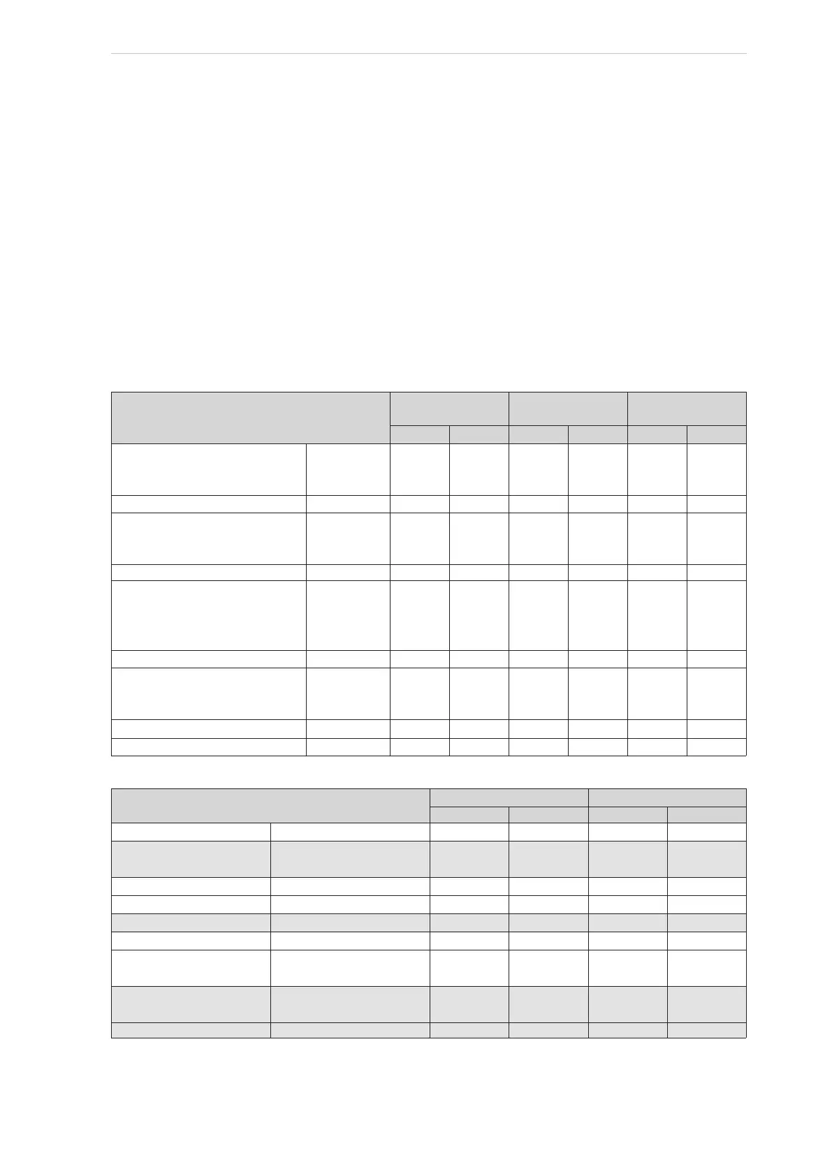
Unit
Type of cooler Inlet Outlet
Type
Plates
Water
Refri.
Water
Refri.
SAB 193 S, L High-stage
3HH
116
66
34
DN80
DN50
DN50
DN80
DN50
DN50
DN80
DN50
DN50
DN80
DN50
DN50
SAB 193 S, L
Booster
3HH 34 DN50 DN50 DN50 DN50
SAB 233 S
High-stage
3HH
116
66
34
DN80
DN50
DN50
DN80
DN50
DN50
DN80
DN50
DN50
DN80
DN50
DN50
SAB 233 S
Booster
3HH 34 DN50 DN50 DN50 DN50
SAB 233 L, E High-stage
3HH
146
116
66
34
DN100
DN80
DN50
DN50
DN80
DN80
DN50
DN50
DN80
DN80
DN50
DN50
DN100
DN80
DN50
DN50
SAB 233 L, E
Booster
3HH 34 DN50 DN50 DN50 DN50
SAB 283 S, L, E, X High-stage
3HH
146
116
34
DN100
DN80
DN50
DN80
DN80
DN50
DN80
DN80
DN50
DN100
DN80
DN50
SAB 283 S, L, E, X
High-stage
4HH
120 DN100 DN100 DN100 DN100
SAB 283 S, L, E
Booster
3HH 34 DN50 DN50 DN50 DN50
Table 7: Oil cooler data
Unit
Type of cooler Connection
Dia. Plates Inlet Outlet
SAB 193 S, L
High-stage
14 in. 116 3 in. 3 in.
SAB193 S, L and SAB
233 S, L, E
Booster 14 in. 66 2 in. 2 in.
SAB 233 S, L
High-stage
14 in. 190 3 in. 3 in.
SAB 233 E
High-stage
14 in. 288 3 in. 4 in.
SAB 283 S, L
Booster
24 in. 56 3 in. 3 in.
SAB 283 S, L
High-stage
24 in. 136 4 in. 5 in.
SAB 283 E, X and SAB
355 S, L
High-stage
24 in. 188 4 in. 5 in.
SAB 283 E, X and SAB
355 S, L, E
Booster
24 in. 72 3 in. 3 in.
SAB 355 X
Booster
24 in. 136 4 in. 5 in.
Table 8: Oil cooler data
 Loading...

