CCS Smart Equipment Control Board for Single Packaged Unit (SPU) Controller Installation
Instructions
1
Applications
The new SE-SPU101x controllers replace the
RTU-100x controllers. All the RTU100x controllers are
discontinued, including the RTU-1003-0 VAV SPU
controller. The new SEC product offering provides new
controller options.
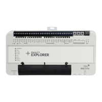
The SE-SPU101x-1 SEC Unit Control Board (UCB) is a
member of the Smart Equipment Controller (SEC)
product family. The controller is designed to run a pre-
engineered HVAC zoning application and provide the
inputs and outputs required for this application.
North American Emissions Compliance
United States
Canada
Installation
Special Tools Needed
• wire strippers
• small flat-head screwdriver
• 22 AWG (0.65 mm) 3-conductor, twisted,
shielded
cabl
e with a drain wire
Note: This drain wire is used only to group the
shielded cable. Do not use this drain wire
as a
conn
ection to the board.
• wire nuts for 22 AWG drain wire
• electrical tape
Mounting
The manufacturing facility mounts the controller. All of
the required power wiring, internal unit sensor wiring,
and output wiring is completed and tested at the
factory. The control application required for the specific
UCB is factory configured and ready for operation.
Wiring
Field Wiring Connections
In addition to power connections, the UCB requires a
communication bus connection. Address selection is
required for networking with a CCS Building
Automation System (BAS).
Power Wiring
The SEC UCB controller is factory wired for 24 VAC
power.
This equipment has been tested and found to
comply with the limits for a Class A digital device
pursuant to Part 15 of the FCC Rules. These limits
are designed to provide reasonable protection
against harmful interference when this equipment is
operated in a commercial environment. This
equipment generates, uses, and can radiate radio
frequency energy and, if not installed and used in
accordance with the instruction manual, may cause
harmful interference to radio communications.
Operation of this equipment in a residential area
may cause harmful interference, in which case the
users will be required to correct the interference at
their own expense.
This Class (A) digital apparatus meets all the
requirements of the Canadian Interference-Causing
Equipment Regulations.
Cet appareil numérique de la Classe (A) respecte
toutes les exigences du Règlement sur le matériel
brouilleur du Canada.
IMPORTANT: The 24 VAC power should not be
shared with other network devices. Sharing power to
other network devices may cause noise,
interference, and ground loop problems. You may
damage the controller by sharing power to other
devices.
CCS Smart Equipment Control Board for Single Packaged
Unit (SPU) Controller
Installation Instructions
SE-SPU1011-1, SE-SPU1012-1
Code No. LIT-12011479
Issued June 16, 2015