EasyManua.ls Logo

Johnson Controls F4-SNC - User Manual

Johnson Controls F4-SNC
26 pages
Print Icon
To Next Page IconTo Next Page
Loading...
F4-SNC Installation Guide
Application
The Facility Explorer SNC Series (F4-SNC) are Ethernet-
based, supervisory controllers that connect Building
Automation System (BAS) networks to IP networks.
The SNC features onboard inputs and outputs for
direct control of equipment. This device monitors and
controls networks of field-level building automation
devices, including HVAC equipment, lighting, security,
and fire safety equipment. The SNC has FIPS 140-2 Level
1 Compliance, which is a United States government
cybersecurity standard that approves cyroptographic
modules/algorithms used for encryption.
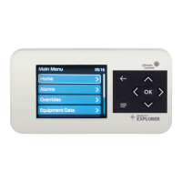
The F4-SNC25151-0H and F4-SNC25151-04H models have a
display where you can view Alarms, Overrides, Equipment
Data, and Trends. You can command Equipment Data
points. Display settings can be viewed and edited but
Controller settings can only be viewed. You can navigate
the display using the direction arrows, back, OK, and menu
buttons.
The F4-SNC25151-0x/x models have a total of 40 I/O points
- with 25 inputs and 15 outputs. The F4-SNC16121-0x
models have a total of 28 I/O points - with 16 inputs and
12 outputs. The first two numbers of the product code
number represent the number of inputs (SNC25151-0x/
x) and the next two numbers represent the number
of outputs (SNC25151-0x/x). The SNC offers various
integration options.
Field Bus integrations supported
BACnet MS/TP
Ethernet integrations supported
BACnet/IP
Physical features
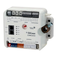
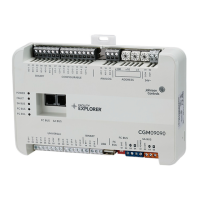
The following figures display the physical features of the
SNC25151-0x/x and SNC16121-0x with display models. The
accompanying table provides a description of the physical
features and a reference to further information where
relevant.
Note: The physical features labelled with callouts
9-16 are only available on SNC models with the
display.
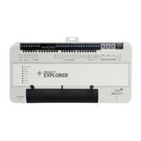
Figure 1: F4-SNC25151-0x/x
*241014302031A*
Part No. 24-10143-02031 Rev. A
2020-11-11
(barcode for factory use only)
F4-SNC25151-0xx, F4-SNC16121-0x

Questions and Answers

  • S
    sshepherdAug 6, 2025
    Why is the FC BUS LED on in my Johnson Controls F4-SNC Controller?
    • M
      Margaret AndersonAug 6, 2025
      If the FC BUS LED on your Johnson Controls Controller is continuously lit, it means that controllers have been defined but none are communicating; the network engine is only transmitting.
  • D
    Denise SpencerAug 12, 2025
    How to fix a solid red USB-1|2 LED on Johnson Controls Controller?
    • E
      Ellen SanchezAug 12, 2025
      If the USB-1|2 LED on your Johnson Controls Controller turns solid red, sequentially remove each USB device until the LED flashes green or turns off. Only approved USB adapters that have been tested and qualified will function correctly with the SNC. Non-qualified adapters are not compatible.
  • A
    Andrew JohnsonAug 17, 2025
    What does it mean when the HEARTBEAT LED is on blue on Johnson Controls F4-SNC Controller?
    • E
      Erika HernandezAug 18, 2025
      If the HEARTBEAT LED on your Johnson Controls Controller is lit blue, it means that power is supplied by 24 VAC, but the controller is non-operational.
  • T
    Thomas MoralesAug 25, 2025
    What does a medium flicker (purple and blue) on the HEARTBEAT LED of a Johnson Controls Controller mean?
    • L
      Lisa RichardsonAug 25, 2025
      If the HEARTBEAT LED on your Johnson Controls Controller has a medium flicker, showing purple and blue, it indicates that the SNC is starting up, blinking at a rate of 2 blinks per second (2 Hz).
  • H
    Heidi PriceAug 30, 2025
    What does a fast flicker (purple and blue) on the HEARTBEAT LED of a Johnson Controls Controller mean?
    • J
      Jasmin MejiaAug 30, 2025
      If the HEARTBEAT LED on your Johnson Controls Controller has a fast flicker, showing purple and blue, it indicates that the SNC is shutting down, blinking at a rate of 5 blinks per second (5 Hz).

Summary

Application

Physical features

Installation

Mounting

Location considerations

Guidelines for selecting an appropriate mounting location for the SNC to ensure optimal performance and longevity.

Wiring overview

Wiring the SNC

CAUTION - Risk of Property Damage

WARNING - Risk of Electric Shock

Connecting to the FC Bus terminal

Connecting the power source

Connecting to the SA Bus port

Connecting input and output terminals

Input and output wiring guidelines

Terminal wiring and cable length guidelines

Provides detailed information on terminal wiring and recommended cable lengths for SNC inputs and outputs.

Communications Bus and supply terminal blocks, functions, ratings, requirements, and cables

Cable length guidelines for recommended wire sizes

Guidelines for selecting appropriate wire sizes and determining maximum cable lengths for SNC connections.

Input;Output wiring validation

Setting the EOL switch

Rotary switch dials

Setting the controller number

LED status indicators

LED test sequence at startup

Reset button

Recovery button

Partition example

Wiring considerations and guidelines

SNC capabilities

SNC ordering information

Accessories ordering information

Repair information

SNC technical specifications

SNC25151-0 x and SNC16121-0 x Display Models Specifications

SNC25151-0 x and SNC16121-0 x Without Display Models Specifications

Johnson Controls F4-SNC Specifications

General IconGeneral
ModelF4-SNC
CategoryController
Controller TypeNetwork Controller
Input Voltage24 VAC/VDC
Communication ProtocolBACnet/IP
Operating SystemLinux
Power Consumption5 W
Enclosure RatingIP20
ProcessorARM Cortex-A8
Dimensions5.6 x 4.8 x 2.4 in.
Weight0.9 lb
Operating Temperature-40°C to 70°C
Humidity Range5 to 95% RH, noncondensing

Related product manuals