Do you have a question about the Johnson Controls F4-CG Series and is the answer not in the manual?
FCC and Canadian compliance statements for digital devices.
Lists included parts, tools, and basic installation requirements.
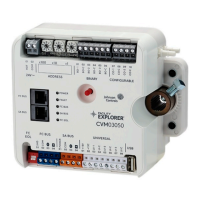
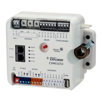
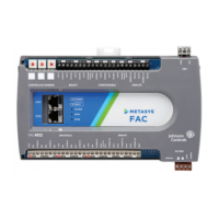
Visual guide to the CGM controller's physical features and connections.
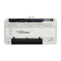
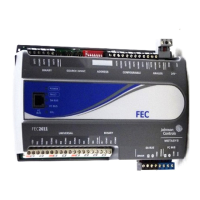
Visual guide to the CGE controller's physical features and connections.
Best practices for controller mounting on surfaces and DIN rails.
Guidance on preferred mounting positions for optimal performance.
Step-by-step instructions for mounting on a 35 mm DIN rail.
Step-by-step instructions for mounting on a wall or flat surface.
Ways CGE controllers connect to BACnet networks via Ethernet.
Wiring and connection details for the FC Bus terminal block on CGM controllers.
Wiring and connection details for the SA Bus terminal block.
Wiring specifications for the 24 VAC supply power terminal block.
Specific guidelines for wiring controller inputs and outputs.
Chart relating cable length, wire size, and load current for inputs/outputs.
Recommended cable types and lengths for FC and SA bus connections.
Specific wiring details for the 24 VAC supply power connection.
Diagrams showing various input connections (e.g., sensors, voltage).
Diagrams showing various output connections (e.g., actuators).
Diagrams illustrating different current input wiring configurations.
Diagrams illustrating binary output wiring configurations.
Diagrams illustrating 0-10 VDC output wiring.
Diagrams illustrating 24 VAC Triac output wiring.
Diagrams illustrating analog output wiring.
Diagrams illustrating incremental control output wiring.
Diagrams illustrating 24 VAC binary output wiring.
Diagrams for connecting Network Stats via SA Bus.
Diagrams for addressable network stat SA Bus connections.
Diagrams for fixed address network stat SA Bus connections.
Steps to configure CGM controllers for N2 protocol communication.
Procedure to switch CGM controllers from N2 to BACnet MS/TP mode.
Steps to configure CGM controllers for wireless field bus systems.
How to set valid and unique device addresses for CGM controllers.
Step-by-step guide to safely remove terminal blocks from the controller.
How to set unique controller numbers for CGE models using rotary switches.
Steps to safely remove the controller housing cover.
Procedure to set the End-of-Line switch on CGM controllers for bus termination.
How to configure UI current loop jumpers for 4-20mA analog inputs.
How to set up local displays for controller I/O monitoring.
Validating wiring using the controller's default operational state.
Steps for commissioning controllers using CCT software and connection types.
Observing LED status indicators for diagnosing controller problems.
List of available accessories for CG series controllers.
Products required for wireless field bus installations.
Specifications for various power supply transformers.
Details on power requirements, protocols, and communication buses.
Information on the number and types of inputs and outputs available.
Specifications for controller mounting, dimensions, and weight.
Details on product compliance certifications and warranty.
Patent information and single points of contact worldwide.
How to find and contact local Johnson Controls branch offices.
| Brand | Johnson Controls |
|---|---|
| Model | F4-CG Series |
| Category | Controller |
| Language | English |




 Loading...