CG series technical specifications
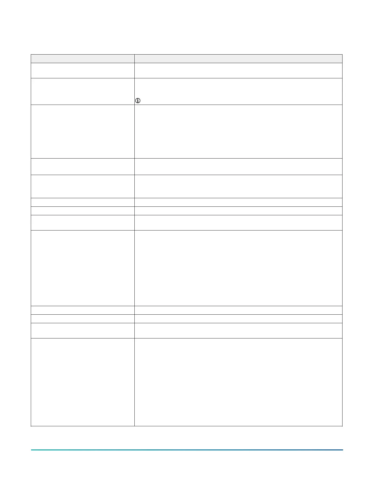
Table 12: Technical specifications for CG series controllers
Specification Description
Power requirement 24 VAC (nominal, 20 VAC minimum/30 VAC maximum), 50/60 Hz, power supply Class 2
(North America), Safety Extra-Low Voltage (SELV) (Europe)
Power consumption
F4-CGM models: 14 VA maximum
1
F4-CGE models: 15 VA maximum
Note: The USB feature is not currently supported.
Power source +15 VDC power source terminals provide 100 mA total current.
F4-CGM09090, F4-CGE09090:
Two +15VDC power sources terminal located in Universal IN terminals for active (3-wire)
input devices
F4-CGM04060, F4-CGE04060:
One +15VDC power sources terminal located in Universal IN terminals for active (3-wire)
input devices
Ambient conditions Operating: 0°C to 50°C (32°F to 122°F); 10 to 90% RH noncondensing
Storage: -40°C to 80°C (-40°F to 176°F); 5 to 95% RH noncondensing
Communications protocol F4-CGM models: BACnet MS/TP, N2, ZFR Wireless also supported (at FC Bus and for
Sensors) with additional hardware.
F4-CGE models: BACnet/IP or BACnet/SC
Device addressing for BACnet MS/TP Decimal address set using three rotary switches: valid controller device addresses 4-127
Device addressing for N2 Decimal address set using three rotary switches: valid controller device addresses 1-254
Controller number for Ethernet
controllers
Three rotary switches to assign a unique number for each controller to physically identify
the controller and relate it to the building drawings; valid controller numbers 0-999
Communications bus F4-CGM models
BACnet MS/TP (default); N2
3-wire FC Bus between the supervisory controller and equipment controllers
F4-CGE models
BACnet/IP (default); BACnet/SC
Two Ethernet ports; 10/100 Mbps; 8-pin RJ-45 connector
All F4-CG models
4-wire SA Bus between equipment controller, network sensors and other sensor/actuator
devices, includes a lead to source 15 VDC supply power, from equipment controller, to bus
devices.
Processor RX64M Renesas
®
32-Bit microcontroller
Memory 16 MB flash memory and 8 MB SDRAM
Real-time clock backup power supply Super capacitor maintains power to the onboard real-time clock for a minimum of 72
hours when supply power to the controller is disconnected.
Input and Output capabilities F4-CGM09090, F4-CGE09090
7 - Universal Inputs: Defined as 0–10 VDC, 4–20 mA, 0–600k ohms, or Binary Dry Contact
2 - Binary Inputs: Defined as Dry Contact Maintained or Pulse Counter/Accumulator Mode
4 - Configurable Outputs: Defined as 0-10 VDC or 24 VAC Triac BO
2 - Analog Outputs: Defined as 0–10 VDC or 4–20 mA
3 - Binary Outputs: Defined as 24 VAC Triac (external power source only)
F4-CGM04060, F4-CGE04060
3 - Universal Inputs: Defined as 0–10 VDC, 4–20 mA, 0–600k ohms, or Binary Dry Contact
1 - Binary Inputs: Defined as Dry Contact Maintained or Pulse Counter/Accumulator Mode
4 - Configurable Outputs: Defined as 0-10 VDC or 24 VAC Triac BO
2 - Binary Outputs: Defined as 24 VAC Triac (external power source only)
F4-CG Series General Purpose Application Controllers Installation Guide 25