Mounting features and dimensions
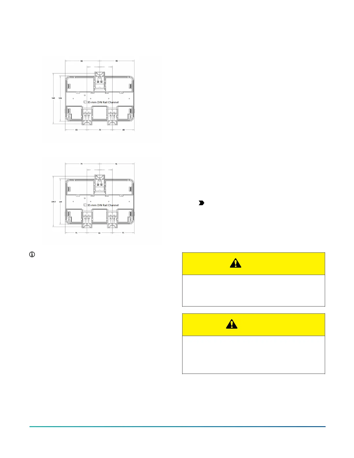
Figure 4: Back of CGE09090 and CGM09090 controller
Figure 5: Back of CGE04060 and CGM04060 controller
Note:
• Mounting dimensions are listed in millimeters in
the above figures.
• The DIN rail channel and the mounting clips are
shown in an extended position.
DIN rail mount applications
About this task:
To mount a controller horizontally on a 35 mm DIN rail
(recommended method), complete the following steps:
1. Securely mount a 20 cm (8 in.) or longer section
of 35 mm DIN rail horizontal and centered in the
desired space so that the controller mounts in the
horizontal position.
2. Pull the two bottom mounting clips outward from
the controller to the extended position (Figure 4 or
Figure 5).
3. Hang the controller on the DIN rail by the hooks at
the top of the (DIN rail) channel on the back of the
controller (Figure 4 or Figure 5), and position the
controller snugly against the DIN rail.
4. Push the bottom mounting clips inward (up) to
secure the controller on the DIN rail. To remove
the controller from the DIN rail, pull the bottom
mounting clips out to the extended position and
carefully lift the controller off the DIN rail.
Wall mount applications
About this task:
To mount a controller directly on a wall or other flat
vertical surface, complete the following steps:
1. Pull the two bottom mounting clips outward and
ensure they are locked in the extended position as
shown in Figure 4 or Figure 5.
2. Determine the proper mounting position the
controller will be installed. Mark the mounting
hole locations on the wall using the dimensions
for the controller listed in Mounting features and
dimensions, or hold the controller up to the wall or
surface in a proper mount position and mark the
hole locations through the mounting clips.
3. Drill holes in the wall or surface at the marked
locations, and insert appropriate wall anchors in
the holes (if necessary).
4. Hold the controller in place, and insert the screws
through the mounting clips and into the holes (or
anchors). Carefully tighten all of the screws.
Important: Do not over-tighten the mounting
screws. Over-tightening the screws may
damage the mounting clips.
Wiring
Observe the following guidelines when wiring a CGM/CGE
controller:
CAUTION
Risk of Electric Shock:
Disconnect the power supply before making electrical
connections to avoid electric shock.
ATTENTION
Mise En Garde: Risque de décharge électrique:
Débrancher l'alimentation avant de réaliser tout
raccordement électrique afin d'éviter tout risque de
décharge électrique.
F4-CG Series General Purpose Application Controllers Installation Guide4