Table 1: Physical features of CGx series controllers
Physical feature: description and references
1 Binary Outputs (BO) Terminal Block: Black terminals. See Table 3.
2 Configurable Outputs (CO) Terminal Block: Black terminals. See Table 3.
3 Analog Output (AO) Terminal Block: Black terminals. Only present on CGM09090 and CGE09090 models. See Table 3.
4 Rotary Switch Block:
CGM: Decimal Addressing. See Setting the device address on CGM models.
CGE: Controller Number. See Setting the controller number for CGE models
5 Supply Power Terminal Block: Gray terminals; 24 VAC, Class 2. See Supply power terminal block.
6 Keypad with Directional Arrows, Back, and Menu Buttons (only available on models with product codes ending in -0H)
7 Cover Lift Tab. See Removing the controller cover.
8 Color display screen (only available on models with product codes ending in -0H)
9 Sensor Actuator (SA) Bus Terminal Block: Orange terminal. See SA Bus terminal block.
10 Field Controller (FC) Bus Terminal Block: Blue terminal. See FC Bus terminal block on CGM controllers.
11 End-of-Line (EOL) Switch. See Setting the End-of-Line (EOL) switch (CGM models only).
12 Universal Serial Bus (USB) 2.0 host type A Port
Note: The USB feature is not currently supported.
13 Binary Input (BI) Terminal Block: White terminals. See Table 3.
14 Universal Inputs (UI) Terminal Block: White terminals. See Table 3.
15 Sensor (SA Bus) Port: RJ-12 6-Pin Modular Jack. See Sensor (SA Bus) port.
16 LED Status Indicators. See LED status and states.
17 FC Bus Port RJ-12 6-pin Modular Jack. See FC Bus port on CGM controllers.
18 Ethernet Ports: ETH-1 and ETH-2. See BACnet/SC or BACnet/IP Ethernet Network Topology for CGE controllers
Mounting
Observe the following guidelines when mounting a
controller:
• Ensure the mounting surface can support the
controller, DIN rail, and any user-supplied enclosure.
• Mount the controller horizontally on 35 mm DIN rail
whenever possible.
• Mount the controller in the proper mounting position.
• Mount the controller on a hard, even surface whenever
possible in wall-mount applications.
• Use shims or washers to mount the controller securely
and evenly on the mounting surface.
• Mount the controller in an area free of corrosive vapors
and observe the Ambient Conditions requirements in
Table 12.
• Provide for sufficient space around the controller for
cable and wire connections for easy cover removal
and good ventilation through the controller (50 mm
[2 in.] minimum on the top, bottom, and front of the
controller).
• Do not mount the controller on surfaces prone to
vibration, such as ductwork.
• Do not mount the controller in areas where
electromagnetic emissions from other devices or wiring
can interfere with controller communication.
On panel or enclosure mount applications, observe the
following additional guidelines:
• Mount the controller so that the enclosure walls do
not obstruct cover removal or ventilation through the
controller.
• Mount the controller so that the power transformer
and other devices do not radiate excessive heat to the
controller.
• Do not install the controller in an airtight enclosure.
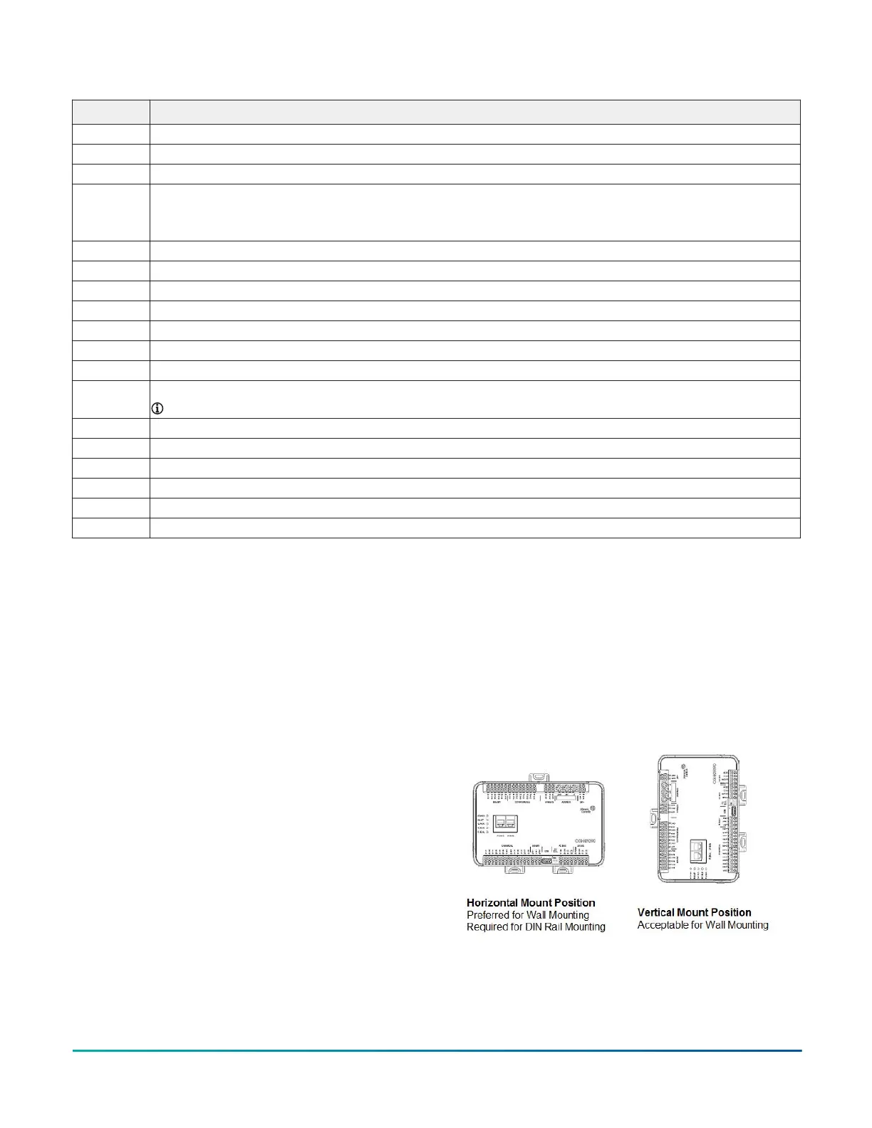
Figure 3: Controller mounting position
F4-CG Series General Purpose Application Controllers Installation Guide 3