2. Pivot the top of the cover further to release it from
the lower two latches.
3. Replace the cover by placing it squarely over the
base, and then gently and evenly push the cover
on to the latches until they snap into the latched
position.
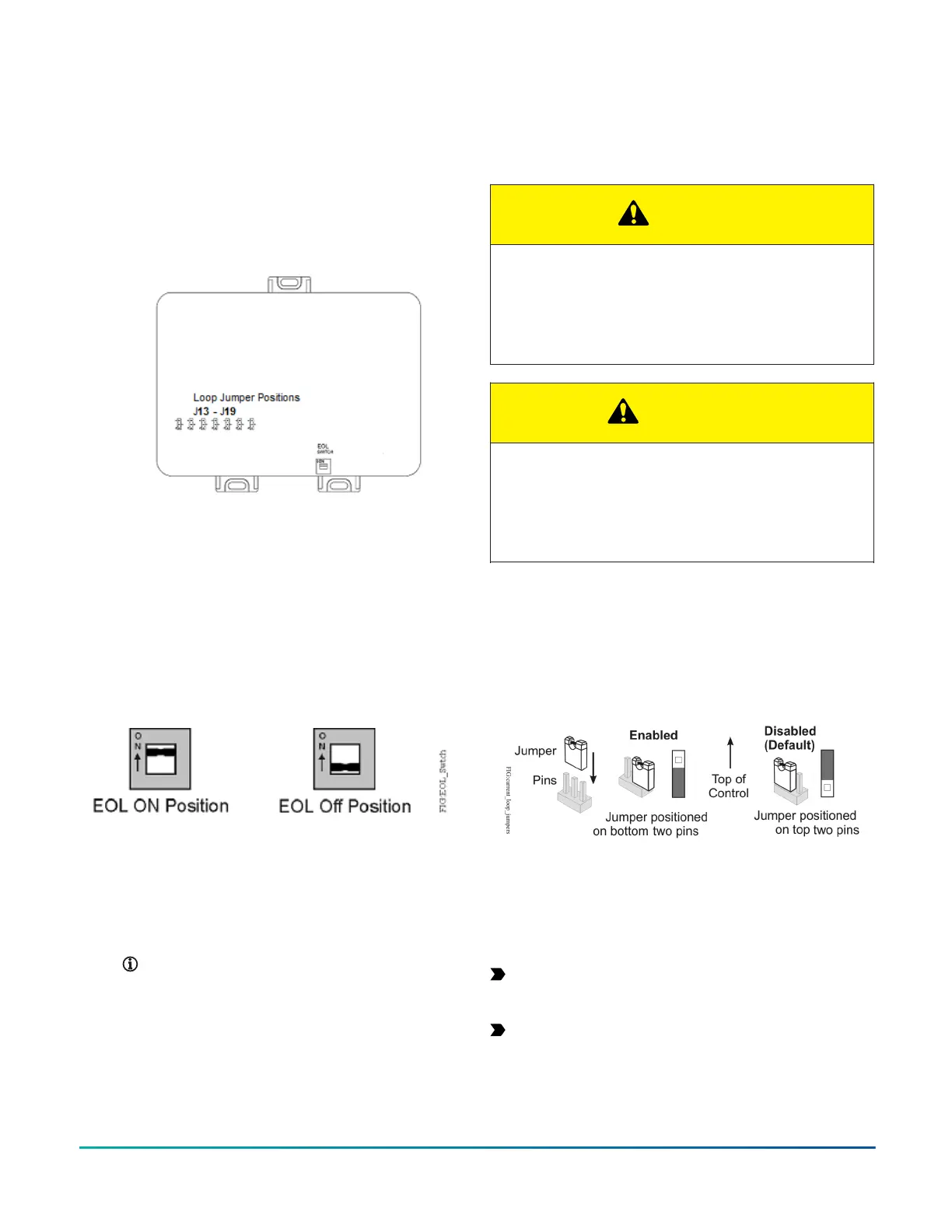
Figure 13: Controller with cover removed showing
jumper positions (CGM09090 model shown)
Setting the End-of-Line (EOL) switch
(CGM models only)
About this task:
Each CGM controller has an EOL switch, which, when set
to ON (up), sets the controller as a terminating device on
the bus. See Figure 13 for the EOL switch location. The
default EOL switch position is OFF (down).
Figure 14: End-of-Line switch positions
To set the EOL switch on a controller, complete the
following steps:
1. Determine the physical location of the controller on
the FC Bus.
2. Determine if the controller must be set as a
terminating device on the bus.
Note: For detailed information about
EOL termination rules and EOL switch
settings on FC Buses, refer to the FX MS/
TP Communications Bus Technical Bulletin
(LIT-12011670).
3. If the controller is a terminating device on the FC
Bus, set the EOL switch to ON. If the controller is
not a terminating device on the bus, set the EOL
switch to Off.
When a controller is connected to power with its
EOL switch set to ON, the amber EOL LED on the
controller cover is illuminated.
Setting the UI current loop jumpers
CAUTION
Risk of Electric Shock:
Disconnect supply power to the devices before
attempting to adjust the UI current loop jumpers.
Failure to disconnect the supply power may result in
electric shock.
ATTENTION
Mise En Garde: Risque de décharge électrique:
Débrancher l'alimentation de l'controller avant tout
réglage du UI current loop jumpers. Le non-respect de
cette précaution risque de provoquer une décharge
électrique.
The UI current loop jumpers are on the circuit board
under the controller cover near the UI terminals (Figure
13). When a UI is defined (in the system software) as a
4-20 mA Analog Input, set the UI's current loop jumper to
the Enabled position (Figure 15).
Figure 15: UI Current Loop Jumper Positions
Setting the current loop jumper to the Enabled position,
connects an internal 100 ohm resistor across the UI
terminals, which maintains the 4-20 mA current loop
circuit even when power to the controller is interrupted or
off.
Important: Current Loop jumpers must be in the
Disabled (default) position for all UIs that are not set
up to operate as 4-20 mA analog inputs.
Important: A current loop jumper must be in the
Enabled position to maintain a closed 4-20 mA
current loop.
The following tables identify the current loop switches
associated with each UI on the CG series controllers.
F4-CG Series General Purpose Application Controllers Installation Guide20