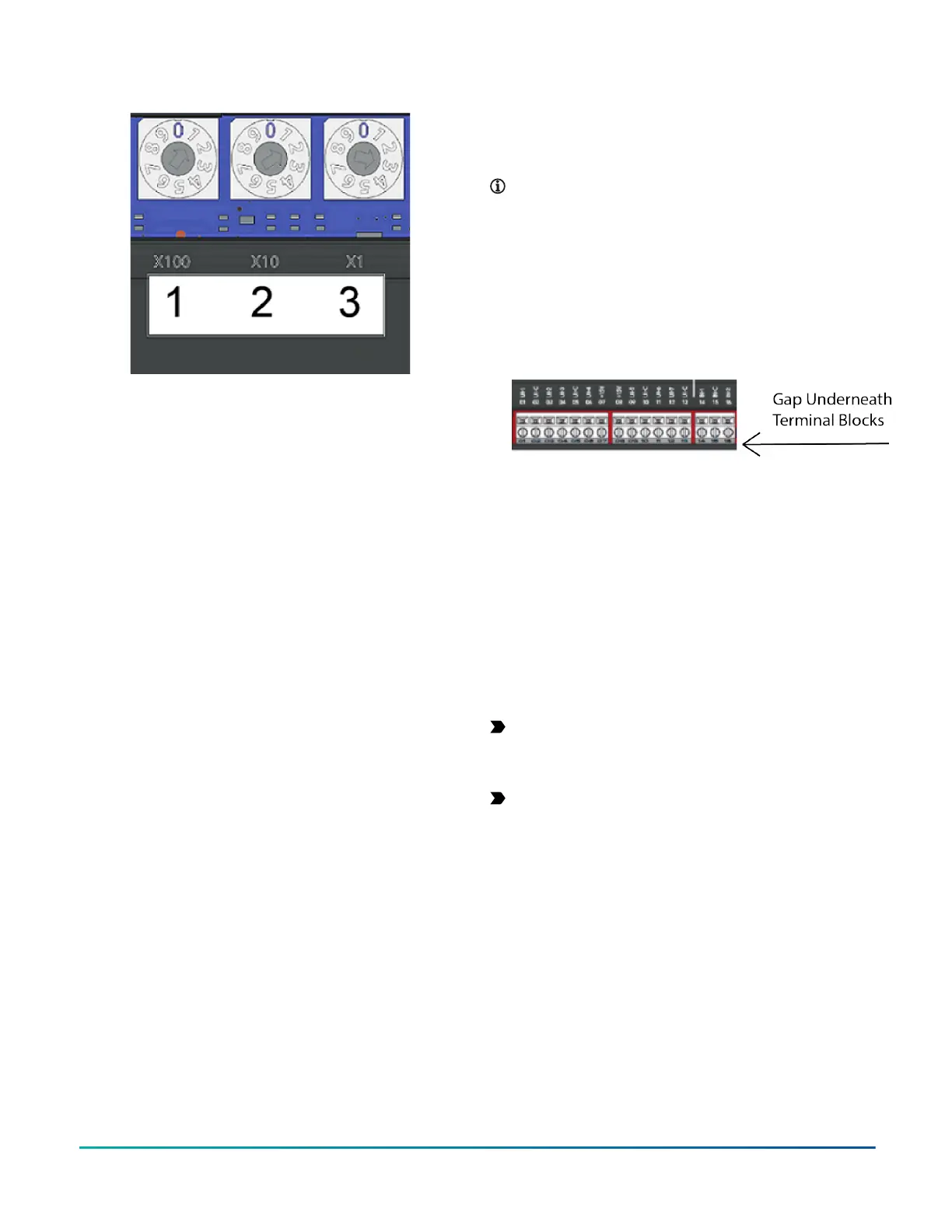
Figure 11: Rotary switch block
The device address must match the device address
defined in the Controller Configuration Tool (CCT) under
Define Hardware > Network Settings.
To set the device addresses on controllers, complete the
following steps:
1. Set a unique and sequential device address for each
of the devices connected on the FC or SA, starting
with device address 4.
2. To ensure the best bus performance, set sequential
device addresses with no gaps in the device address
range (4, 5, 6, 7, 8, 9, and so on). The devices do not
need to be physically connected on the bus in their
numerical device address order.
3. Write each controller's device address on the white
label below the Device Address Rotary Switch Block
on the controller's cover.
For more information about controller device addresses
and how to set them on MS/TP buses, refer to the FX MS/
TP Communications Bus Technical Bulletin (LIT-12011670).
Setting the controller number for CGE
models
The rotary switches on the CGE models are used to set the
controller number. The controller number can be utilized
to physically identify the controller and relate it to the
building drawings. The factory default BACnet device ID is
calculated from the value of the controller number added
to 2000000. Each equipment controller on a BACnet/SC
or BACnet/IP network must have a unique BACnet device
ID on the subnet where it resides in order for proper
identification and communication. To ensure a unique
value, the BACnet device ID should be configured in CCT
instead of relying on this default calculation. This step
will be necessary on sites with more than 1000 devices as
controller numbers will be duplicated.
The controller number is set using three rotary switches
and may be numbered from 000 to 999. The numbers are
ordered from left to right: 100s, 10s, and 1s.
In Figure 11, the switches are set to 1 2 3, designating
this controller as controller number 123. The controller
number can be written in the white squares provided so
the controller number can be more easily seen from a
distance.
Removing a terminal block
About this task:
To remove a terminal block from the circuit board,
complete the following steps:
Note: You need a flat blade screwdriver to remove
the terminal block.
1. To prevent any possibility of damage from an
accidental short, remove power from the
controller.
2. Underneath the terminal block, in the small gap
between the bottom of the terminal block and
the circuit board, insert the flat blade of the
screwdriver.
Figure 12: Terminal block
3. To detach the left-hand side of the terminal block,
position the flat blade underneath the terminal
block to the left, and push down the screwdriver
handle. When you do this, you are using the
screwdriver as a lever to pry up the terminal block.
4. To detach the right-hand side of the terminal block,
position the flat blade underneath the terminal
block to the right, and push down the screwdriver
handle.
5. If necessary, repeat steps 3 and 4 until the terminal
block is removed.
Removing the controller cover
About this task:
Important: Electrostatic discharge can damage
controller components. Use proper electrostatic
discharge precautions during installation, setup, and
servicing to avoid damaging the controller.
Important: Disconnect all power sources to the
controller before removing the cover and changing
the position of any jumper on the controller. Failure
to disconnect power before changing a jumper can
result in damage to the controller and void any
warranties.
The controller cover is held in place by four plastic latches
that extend from the base and snap into slots on the
inside of the housing cover.
To remove the controller cover, complete the following
steps:
1. Place your fingertips under the two cover lift tabs
(Physical features) on the sides of the housing
cover and gently pry the top of the cover away
from the base to release the cover from the two
upper latches.
F4-CG Series General Purpose Application Controllers Installation Guide 19