Troubleshooting equipment
controllers
Observe the Status LEDs on the front of the equipment
controller. Table 10 provides LED status indicator
information for troubleshooting the controller. To
troubleshoot an integral or local controller display, refer
to the FX-DIS1710 Local Controller Display Technical Bulletin
(LIT-12011666).
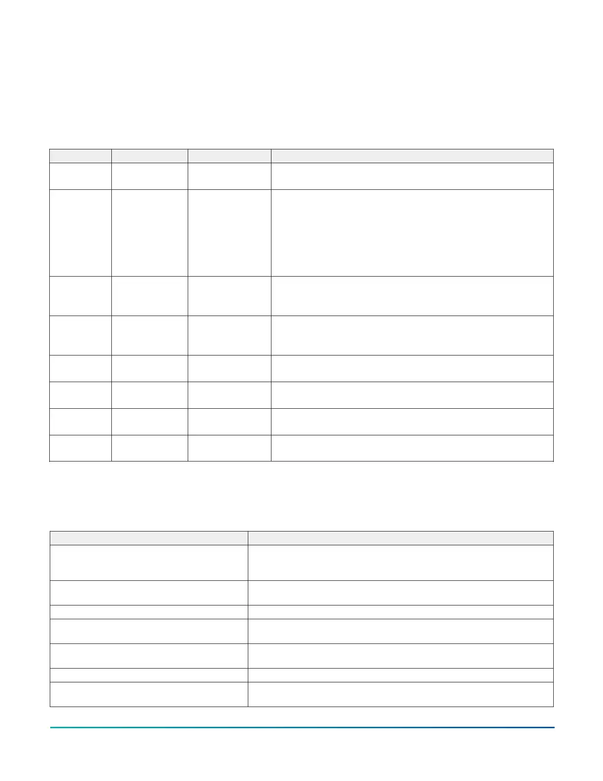
LED status and states
Table 10: Status LEDs and description of LED states
LED label LED color Normal state Descriptions of LED states
POWER Green On Steady Off Steady = No power
On Steady = Power is supplied by primary voltage
FAULT Red Off Steady 2 blinks followed by long pause = Controller powered on in default state.
For more information about this default state, see Input/Output wiring
validation.
Blink - 2 Hz = Startup in progress, not ready for normal operation
Rapid blink = SA Bus communications issue
Off Steady = No faults
On Steady = Device fault or no application loaded
FC BUS (CGM
models)
Green Blink - 2 Hz Blink - 2 Hz = Data transmission (normal communication)
Off Steady = No data transmission (auto baud in progress)
On Steady = communication lost, waiting to join communication bus
SA BUS Green Blink - 2 Hz Blink - 2 Hz = Data transmission (normal communication)
Off Steady = No data transmission (N/A - auto baud not supported)
On Steady = Communication lost; waiting to join communication bus
FC EOL (CGM
models)
Amber Off (except on
terminating devices)
On Steady = EOL is active
Off Steady = EOL is not active
ETH-1 (CGE
models)
Green Off Off Steady = ETH-1 is not connected
Blinking = ETH-1 connected and communicating
ETH-2 (CGE
models)
Green Off Off Steady = ETH-2 is not connected
Blinking = ETH-2 connected and communicating
FAULT and
SA BUS
Red
Green
Both blink six times in sequence = no valid firmware on the device
(Applicable to CGE models only)
Accessories
The following table provides the product code number for
the CG series controller accessories.
Table 11: CG series controller accessories (order separately)
Product Code Number Description
XPM Series Expansion Modules Refer to the Facility Explorer CG, CV Equipment Controllers and XPM Expansion
Modules Product Bulletin (LIT-12013225) for a complete list of available XPM series
expansion modules.
PCX Series Expansion Modules Refer to the PCX Input/Output Expansion Modules Catalog Page (LIT-1900671) for a
complete list of available PCX series expansion modules
TL-CCT-0 License enabling Controller Configuration Tool (CCT) software for one user
FX-FCP-0 License enabling Facility Explorer Equipment Controller Firmware Package Files
required for CCT
Mobile Access Portal (MAP) Gateway Refer to the Mobile Access Portal Gateway Catalog Page (LIT-1900869) to identify the
appropriate product for your region.
F4-DLK0350-0 Local Controller Display, 3.5 in. (89 mm) color display with navigation keypad
FX-DIS1710-0 Local Controller Display, 3.0 in. (76 mm) monochrome display with navigation
keypad
F4-CG Series General Purpose Application Controllers Installation Guide22