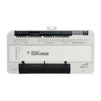
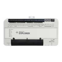
CCS Smart Equipment Control Board for Single Packaged Unit (SPU) Controller Installation Instructions 7
Correcting Physical Communication Bus Problems
The communication bus is subject to a number of
physical factors that can affect performance. Consider
the following list of common physical problems that
affect the communications bus:
• Check wires
- Verify that the wire is 22 AWG (0.65 mm) 3-
conductor, twisted, shielded cable.
- Verify that the shield is continuous and hard-
grounded at one end.
• Check wiring
- Check for and eliminate T-Taps (wire
configurations that create a T shape) and star
configurations.
- Ensure that the bus is wired in daisy-chain
fashion.
- Verify that appropriate devices have three
wires entering and exiting each terminal.
(Devices at the ends of the trunk do not have
this wiring.)
• Check EOL switch settings
- Verify that the zone bus EOL switch on the
Zone Coordinator is set to ON and the Zone
Coordinator is located at the end of the zone
bus trunk.
- Verify that only the EOL switch at the end of
the system bus is set to ON and all other
system bus EOL switches are set to OFF.
• Check connections, polarity, and lengths
- Verify that communications loops are less than
approximately 304 m (1,000 ft) total in length
- If you are using one transformer to power
multiple devices, verify that the device 24 VAC
power connection follows the polarity of the
common and 24 V terminations (see Power
Wiring).
• Check for opens and shorts
• Check terminations
• Check addresses
- Check for duplicate addresses.
- Verify that the address range is sequential.
• Check for sources of interference
• Check the status LED to verify power at the
controller.
• Check bus voltages:
- (+) to COM must be within 2.0 to 3.0 VDC
- (-) to COM must be within 1.5 to 2.54 VDC
- (+) to (-) must be within 0.3 to 1.0 VDC
Note: Values may fluctuate due to ongoing
communications; this operation is normal provided
the voltage is within the defined range.
Repair Information
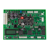
If the Unit Control Board (UCB) fails to operate within
its specifications, replace the unit. For a replacement
controller, contact the nearest Johnson Controls®
representative.
 Loading...

