04: lock the keys except on/off
4
T7000
Item
T7600-
TF21-
...JS0
T7601-
TF20-
...JS0
T7600-
TF20-
...JS0
T7603-
T000-
...JF0
T7600-
TB21-
...JA0
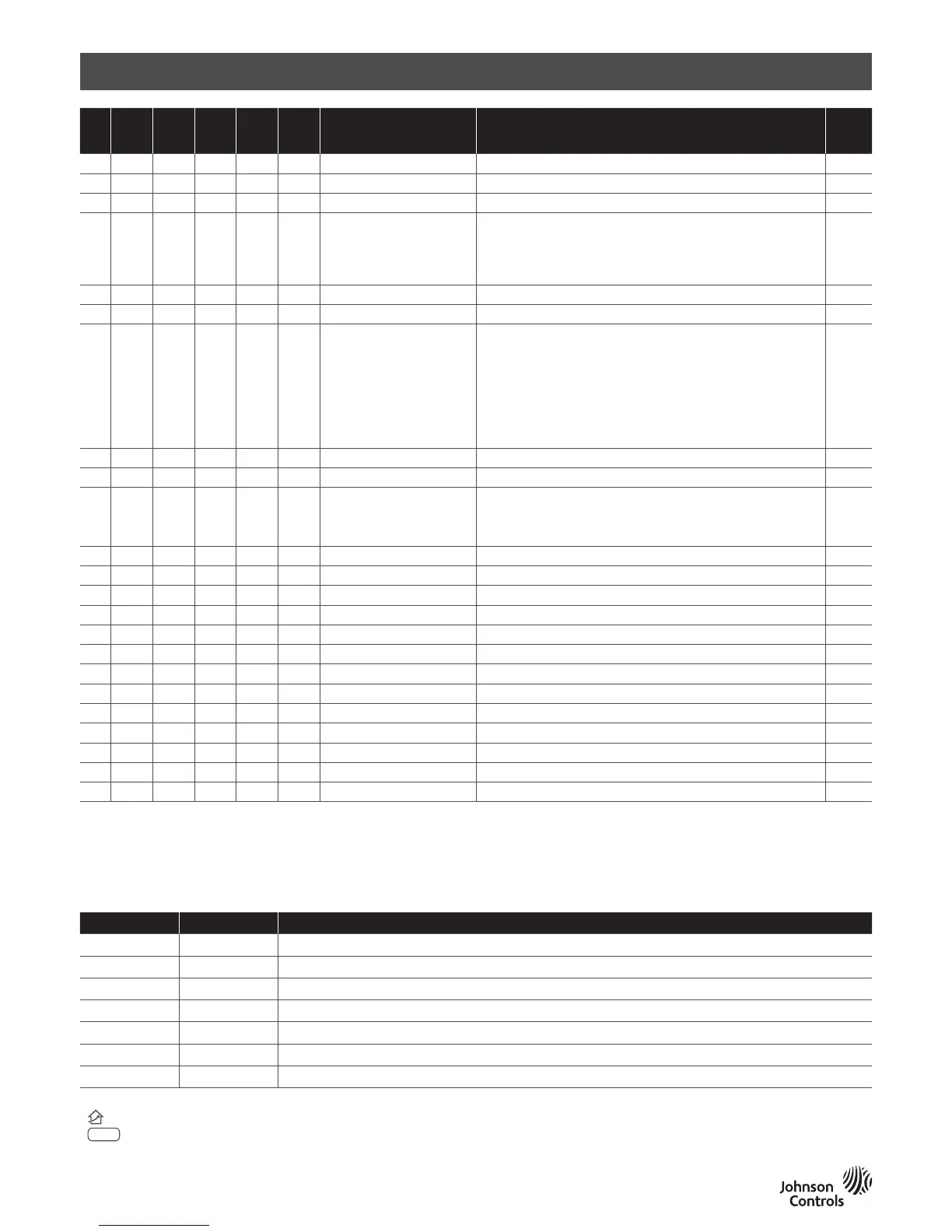
Parameter Function Default
11 ■
ECM Max voltage Max voltage above which the fan output is 100%, range 0-10V. 10V
12 ■
ECM cut off relay 00: Disabled; 01: Enabled 00
13 ■ ■ ■ ■ ■
Restart after power failure 00: keep last status; 01: on; 02: off 00
14 ■ ■ ■ ■ ■
Keypad lock
00: no lock;
01: lock all keys;
02: lock the keys except fan speed and temp. adjustment;
03: lock on/off and general;
00
15 ■ ■ ■ ■ ■
Default display 00: display room temp.; 01: display set point only 00
16 ■ ■ ■ ■
Auto changeover 00: disable; 01: enable (When 2 pipe requires 10K NTC on water tube) 00
17 ■ ■ ■ ■ ■
Digital input function
00: open indicates key card is inserted (occupied), closed indicates key
card is pulled out (unoccupied);
01: closed indicates key card is inserted (occupied), open indicates key
card is pulled out (unoccupied);
02: closed indicates dew point risk, open indicates no dew point risk;
03: open indicates dew point risk, closed indi-cates no dew point risk;
04: open indicates occupied, closed indicates unoccupied, shut off fan
and valve;
05: closed indicates filter alarm; 06: open indicates filter alarm
00
18 ■ ■ ■ ■ ■
Unit selection 00: Celsius degree (℃); 01: Fahrenheit degree (
o
F
) 00
19 ■ ■ ■ ■ ■
Temperature offset Setting range –5~5℃(-9~9
o
F
) 0
20 ■ ■ ■ ■
Fan speed
00: 3 speed;
01: 2 speed (wiring MED, LOW);
02: 1 speed (wiring LOW);
03: no fan
00
21 ■ ■ ■ ■ ■
Language 00: Chinese; 01: English 00
22 ■ ■ ■ ■
Mode selection 00: cooling/heating/ventilation; 01: cooling only; 02: heating 00
23 ■ ■ ■ ■ ■
Back light The back light will be OFF in 05 ... 60 Sec 30
25 ■ ■ ■ ■ ■
Remote sensor type 00: China market 10KNTC; 01: JCI type II 10kNTC 00
26 ■ ■ ■ ■ ■
MODBUS address 1-64 1
27 ■ ■ ■ ■ ■
Baud rate 00: 9600; 01: 4800 00
28 ■ ■ ■
Sample time Setting range 1~99s 10
29 ■ ■ ■ ■ ■
Deadband Setting range 0~10℃ 1
30 ■ ■ ■
KP Setting range 1~99 10
31 ■ ■ ■
KI Setting range 0~99 01
32 ■ ■
TiO2/ESP operation 00: operate separately (corresponding button); 01: work with FCU fan 00
33 ■ ■
Inter stage difference Setting range 0~10℃ 3
34 ■ ■
Heating stage 00: 2 stage; 01: 1 stage 00
• Terminal blocks represent the most common application. Please check the application table first
•
The r
elay output are line voltage, they are connected with line voltage internally inside thermostat
•
The OC
C terminal can assume different meaning depending on parameter 17 setting
• The functionality of the remote NTC is depending by P25 and P16 parameters
Alarm Code Description
Item Code Description
1 E1 Internal sensor shorted warning
2 E2 Internal sensor opened warning
3 HI High temperature warning. Room Temperature > 55℃
4 LO Low temperature warning. Room Temperature < 0℃
5 E3 Remote sensor shorted
6 E4 Remote sensor opened
7 E5 Dew point risk warning
· E3,E4 only available for 2-pipe, auto mode enabled.
·
icon will twinkle if there is filter alarm
·
COM
symbol will ash if there are communication fault
· If the remote sensor is enabled, the E1/E2 warning will be ignored. If E1/E2 warning happened, T7000 will shut off the fan and close the valve.