Do you have a question about the Johnson Controls T7200 and is the answer not in the manual?
Details the physical dimensions of the T7200 thermostat and mounting requirements.
Specifies the environmental operating limits for temperature and humidity.
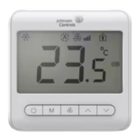
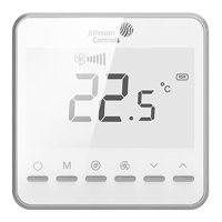
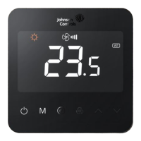
Illustrates typical display modes and icons shown on the T7200 thermostat screen.
Provides a visual guide to the main steps involved in installing the thermostat.
Details wiring for various 2-pipe Fan Coil Units (FCU) with different valve types.
Shows wiring diagrams for 4-pipe Fan Coil Units (FCU).
Illustrates the wiring for an Air Handling Unit (AHU) with a single fan speed.
Presents wiring diagrams for a water source heat pump system.
Wiring configurations for 2-pipe FCUs using V1/V2 terminal designations.
Wiring configurations for 4-pipe FCUs using V1/V2 terminal designations.
Wiring for AHU and heat pump systems using V1/V2 terminal designations.
Wiring examples featuring NTC sensor connections and specific terminal labels.
Defines the symbols and abbreviations used in the wiring diagrams and parameter tables.
Critical safety instructions and warnings regarding electrical shock and proper handling.
Guidelines and procedures for thermostat repair or replacement and warranty voidance.
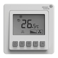
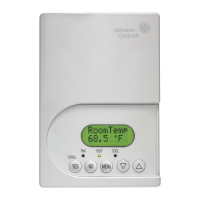
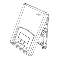
Identifies and describes the buttons, display elements, and features of the T7200 interface.
Covers turning the device on/off, selecting modes, setting temperature, and adjusting fan speed.
Explains keypad locking, unlocking, and Tio2/ESP functionality.
Describes the procedure to enter the parameter setting mode after power off.
Details the first set of configurable parameters (01-14) and their functions.
Details the second set of configurable parameters (15-37) and their functions.
Provides important notes on parameter usage and dependencies on application settings.
Lists all alarm codes (E1, HI, LO, E5, E3, E4) with their descriptions and conditions.
Explains the meaning of specific icons and how alarms affect thermostat operation.
Declaration of compliance with essential requirements of EMC and Low Voltage Directives.
Table detailing the presence of hazardous substances in product components.
Information on product warranty coverage and terms of use for the embedded software.
Provides contact details for local branch offices and general customer support.
| Power Source | 24 VAC |
|---|---|
| Power Method | Hardwired |
| Programs | 7-Day Programmable |
| Backup Battery | No |
| Type | Programmable |