T7200
P/N 24-85784-00186 Rev. C Issue Date: 01 2020
English
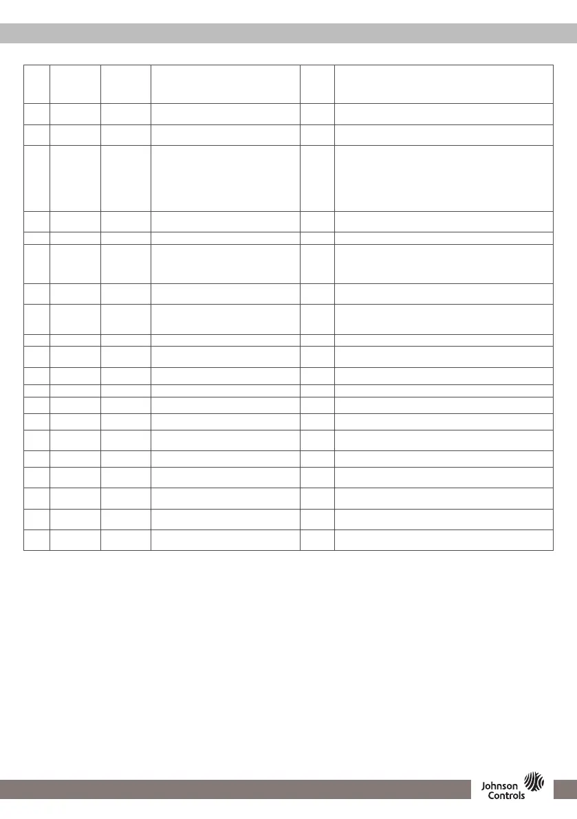
PARAMETER SETTING (PART 2/2)
Code
T7200-
TB21-9JS0,
T7200-
TB21-9JS1
T7200-TF20-
9JS0,
T7200-TF20-
9JS1 Parameter Name Default Function
15
■ ■
Default display 00
00: Display room temp.
01: Display setpoint only
16
■
3
■
3
Auto changeover 00
00: Disable
01: Enable
17
■ ■
Digital input function 00
00: Setpoint reduction when contact is Closed (UnOccupied)
01: Setpoint reduction when contact is Open (UnOccupied)
02: Dew Point Alarm when contact is Closed
03: Dew Point Alarm when contact is Open
04: Shut off Fan and Valves when contact is Closed
05: Filter Alarm when contact is Closed
06: Filter Alarm when contact is Open
18
■ ■
Unit selection 00
00: Celsius degree (°C)
01: Fahrenheit degree (°F)
19
■ ■
Temperature offset 0 Setting range -5°C to 5°C (-9°F to 9°F)
20
■
1
■
1
Fan speed 00
00: 3 Speed
01: 2 Speed (MED, LOW)
02: 1 Speed (LOW)
03: No Fan
21
■ ■
Language 00
00: Chinese
01: English
22
■ ■
Mode selection 00
00: Cooling/heating/ventilation
01: Cooling only
02: Heating
23
■ ■
Back light 30 The back light will be OFF in 05 seconds to 60 seconds.
25
■
8
■
8
Remote sensor type 00
00: China market 10KNTC
01: JCI type II 10NTC
28
■
4
---
Sample time 10 Setting range 1 to 99
29
■ ■
Deadband 1 Setting range 0°C to 10°C (32°F to 50°F)
30
■
4
---
KP 10 Setting range 1 to 99
31
■
4
---
KI 01 Setting range 0 to 99
32
■
5
■
5
TiO2/ESP operation 00
00: Operate separately (Pressing Timer button shortly)
01: Work in parallel with FCU fan
33
■
6
■
6
Inter stage difference 3 Setting range 0°C to 10°C (32°F to 50°F)
34
■
6
■
6
Heating stage 00
00: 2 Stages
01: 1 Stage
35
■
7
---
Set Damper Opening time control 00
00: Disable
01: Enable
36
■
7
---
Damper opening time, 75 - 174 seconds
(only AHU application)
00
00 - 99
(00 = 75 s / 99 = 174 s)
37
■ ■
Fan off timer (time position setting for
fan off)
00 00-99 seconds
Note
• Terminal blocks changes depending on the application selected, please check the table beside rst
• The relay output are line voltage, they are connected with Terminal “L” internally
• The digital input “OCC” can assume dierent meaning depending on parameter 17 setting
1 Appeared when application parameter is 00,01,02,03,04,05,07
2 Appeared when application parameter is 00,01,02,03,04,05
3 Appeared when application parameter is 01 for T7200-TB21-9JS0 and T7200-TF20-9JS0
4 Appeared when application parameter is 06 07
5 Appeared when application parameter is 03
6 Appeared when application parameter is 04
7 Appeared when application parameter is 06
8 Parameter 25 is supported by T7200-TB21-9JS1 and T7200-TF20-9JS1