EasyManua.ls Logo

Johnson Controls T9600 - User Manual

Johnson Controls T9600
13 pages
Print Icon
To Next Page IconTo Next Page
Loading...
T9600
LCD Digital Thermostat
Installation Guide
P/N 24-11447-00004 Rev. B Issue Date: 11 2020
Building Efciency
Headquarters: Milwaukee, Wisconsin, USA
Branch Officies: Principal Cities World-wide
Johnson Controls
®
are registered trademarks of Johnson Controls.
All other marks herein are the marks of their respective owners.
© Copyright 2020 Johnson Controls. All rights reserved. Any unauthorized use or copying is strictly prohibited.
www.johnsoncontrols.com
*241144700004B*
87.77
87.77
60.00
13.83
45.83
> 50 cm
> 150 cm
°C
ON / OFF
AUTO
°C/°F
1s
TiO2/ESP
3s
Timer
Symbol
ON
OFF
ON
OFF
• Ambient
工作环境
MAX
40 °C
104 °F
MIN
0 °C
-32 °F
MAX
60 °C
140 °F
MIN
-10 °C
-14 °F
MAX 90% RH
MIN 10% RH
Question and Answer IconNeed help?

Do you have a question about the Johnson Controls T9600 and is the answer not in the manual?

Johnson Controls T9600 Specifications

General IconGeneral
BrandJohnson Controls
ModelT9600
CategoryThermostat
LanguageEnglish

Summary

T9600 Thermostat Overview

Physical Dimensions

Displays the physical dimensions and measurements of the T9600 thermostat.

Operating Environment

Details the recommended ambient temperature and humidity ranges for thermostat operation.

Key Interface Functions

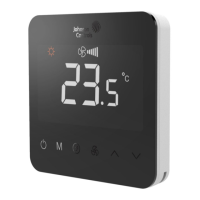
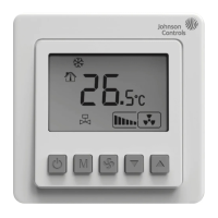
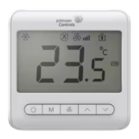
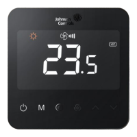
Illustrates basic thermostat controls like ON/OFF, mode selection, and fan speed.

Wiring Diagrams

Standard FCU Wiring Configurations

Wiring diagrams for 2-pipe and 4-pipe FCU relay applications.

Specialty FCU Wiring Configurations

Wiring for FCUs with TiO2/ESP, floor heating, and water source heat pumps.

Advanced FCU Wiring

FCU with ECM Fan and 3-Wire Wiring

Wiring diagrams for FCUs featuring ECM fans and 3-wire relay configurations.

FCU with Special Features and ECM Fans

Wiring for FCUs with TiO2/ESP, floor heating, and water source heat pumps using ECM fans.

FCU and AHU Wiring Diagrams

FCU with ECM Fan and Radiator Wiring

Wiring for FCUs with ECM fans, radiators, and damper control.

AHU Wiring and Legend

Wiring diagram for Air Handling Units and a legend for connection symbols.

Installation and Safety Information

General Installation Guidelines

Covers installation instructions, important notes, and safety warnings for technicians.

T9600 Interface Description

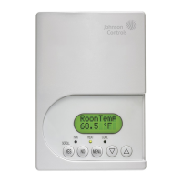
Details the T9600 thermostat interface with labeled buttons and their functions.

Thermostat Operation and User Settings

Basic Operational Controls

Explains On/Off, mode selection, temperature, and fan speed adjustments.

Advanced Operation Features

Covers delay timers, key lock function, and TiO2/ESP manual operation.

Parameter Settings - Part 1

Introduction to user-configurable parameters and their initial settings.

Advanced Parameter Configuration

Parameter Settings - Part 2

Continues the list of user-configurable parameters for the thermostat.

Service Setting Access

Instructions on how to access the service settings menu for advanced configuration.

Service Parameter Settings - Part 1

Details service parameters related to frost protection, application, and setpoints.

System Parameters and Alarms

Parameter Settings - Part 2

Further parameters including hysteresis, BI function, mode restrictions, and fan settings.

Alarm Code Descriptions

Lists and explains various alarm codes generated by the thermostat.

Compliance, Warranty, and Legal Information

Regulatory Compliance

Declaration of compliance with EMC and Low Voltage Directives.

Contact and Legal Terms

Provides contact points, software terms of use, and product warranty information.

Related product manuals