The Johnson Controls T9200 LCD Digital Thermostat is a sophisticated control device designed for managing various HVAC systems. This installation guide, P/N 24-11446-00018 Rev. B, issued in November 2020, provides comprehensive details for its installation, operation, and maintenance.
Function Description
The T9200 thermostat serves as an operating control for a wide range of heating, ventilation, and air conditioning applications. It supports various system configurations, including 2-pipe and 4-pipe FCU (Fan Coil Unit) systems, 2-pipe and 3-wire valve applications, systems with floor heating, TiO2/ESP (Electro-static Precipitator) functionality, water source heat pumps, and boiler/floor heater setups. The device allows users to select different working modes such as cooling, heating, ventilation, and auto (cooling/heating) mode. It also features fan speed adjustment (auto, high, medium, low), temperature setting, and a delay on/off function for scheduled operation. Advanced features include frost protection, unoccupied mode setpoints, ECM (Electronically Commutated Motor) fan control with adjustable minimum and maximum voltages, and a BI-FUNCTION input for various applications like dew point risk, filter alarm, or change-over sensor. The thermostat also incorporates a key-lock function to prevent unauthorized access to settings.
Important Technical Specifications
Dimensions:
- Front panel: 87.77 mm (width) x 87.77 mm (height)
- Depth from wall: 38.83 mm (main body) + 13.83 mm (mounting plate)
- Mounting hole spacing: 60.00 mm
Environmental Limits:
- Ambient Operating Temperature: 0°C to 40°C (32°F to 104°F)
- Ambient Storage Temperature: -10°C to 60°C (14°F to 140°F)
- Humidity: 10% to 90% RH (non-condensing)
Electrical Ratings:
- Power Supply: 100-240 VAC, 50/60Hz
- Output types: Relay outputs are line voltage, connected internally to Terminal "L" (Live).
- ECM Fan Control: 0-10V output for ECM fan speed modulation.
- Digital Input "OCC": Can assume different meanings depending on parameter 12 setting.
Safety and Compliance:
- CE compliant, adhering to essential requirements and other relevant provisions of the EMC Directive and Low Voltage Directive.
- Hazardous Substances: Complies with SJ/T11364 regulations for lead, mercury, cadmium, hexavalent chromium, polybrominated biphenyls (PBB), and polybrominated diphenyl ethers (PBDE).
Usage Features
User Interface:
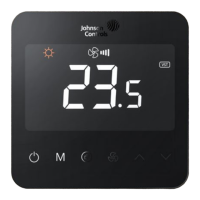
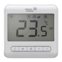
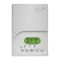
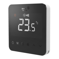
The thermostat features an LCD display with touch buttons for intuitive control.
- Power Button (A): Turns the device on/off, closing the fan and valve.
- Working Mode Button (B): Cycles through cooling (*), heating (☼), ventilation ( ), and auto (A) modes. The auto mode is available for 4-pipe or 2-pipe applications with BI-FUNCTION set to Change Over Sensor input.
- General Button (C): Used in conjunction with other buttons for various settings.
- Fan Speed Adjustment Button (D): Switches fan modes between auto (III flash), high (II), medium (II), and low (I). In Floor Heating Mode, the fan stops unless the FH-FAN parameter is enabled for single-stage floor heating.
- Up and Down Buttons (E): Adjust temperature by 0.5°C/1°F and navigate through parameter lists.
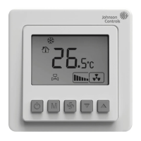
Display Indicators:
The LCD shows current temperature, setpoint, fan speed, operating mode, valve status (VST), remote sensor status (RSR), compressor protection (N), delay time (O), temperature and humidity value (P), low temperature protection (Q), and dehumidify (R). Alarm conditions (J) and lock status (K) are also displayed.
Parameter Settings:
The thermostat offers extensive user and service settings accessible through specific button combinations.
- User Settings: Includes mute, temperature offset, unoccupied cooling/heating setpoints, sample time for PID, proportion band (PB), integration parameter (KI), backlight timer, power-fail restart behavior, TiO2/ESP control (automatic/manual), key-lock function (levels 1-4), temperature display (room temperature/setpoint), and unit selection (°C/°F).
- Service Settings: Provides frost protection, FH-FAN enable/disable, application type selection (e.g., 2-pipe FCU, 4-pipe FCU, water source heat pump), lower/upper setpoint limits, frost protection setpoint, ECM min/max voltage, floor heater stage temperature difference, hysteresis for ON/OFF control, BI-FUNCTION input type, mode restriction (cooling only/heating only), fan restriction (no fan/one/two/three speed), fan operation in deadband, and fan mode in unoccupied.
Alarm Codes:
The device provides alarm codes for various issues:
- E1: Internal sensor warning.
- HI: High temperature warning (>55°C / >131°F).
- LO: Low temperature warning (<0°C / <32°F) or internal sensor opened.
- E5: Dew point risk warning (valves and fan shut off).
- E6: Filter alarm.
- E7: BI warning.
Maintenance Features
Repair and Replacement:
The manual explicitly states that users should not attempt to repair the T9 Series thermostat. In case of malfunction, contact a Johnson Controls representative and provide the product code number. Removing the PCB from the enclosure cover voids the product warranty.
Safety Precautions:
- Always disconnect power supply before making electrical connections to prevent electrical shock.
- Ground the thermostat according to local, national, and regional regulations.
- Insulate and secure any unused wire leads before applying power to prevent electrical shock and property damage.
- Do not install the thermostat in condensing, wet, or damp environments, as moisture can cause damage.
- Ensure all wiring connections comply with local, national, and regional regulations and do not exceed the thermostat's electrical ratings.
Software and Warranty:
- Software use is subject to terms found at www.johnsoncontrols.com/techterms.
- Product warranty details are available at www.johnsoncontrols.com/buildingswarranty.