3. Align the thermostat controller mounting base on
the wall with the security screw on the top and use
the base as a template to mark the two mounting
hole locations. See Figure 3.
- If you need to install the thermostat controller
on an electrical junction box, use2-1/2 x 4 in.
(63 x 101 mm) square boxes with mud ring
covers and avoid smaller 1-1/2 x 4 in.(38 x 101
mm) square or 3 x 2 in. (76 x 51 mm) boxes.
This procedure ensures that you have enough
space for cabling, if needed.
- For surface-mounted applications, use durable
mounting hardware, such as wall anchors, that
cannot be easily pulled out of the mounting
surface.
4. Pull approximately 6 in. (152 mm) of wire from the
wall and insert the wire through the center hole
in the thermostat controller mounting base. See
Figure 3.
5. Secure the mounting base to the wall surface using
two mounting screws (user supplied) as illustrated
in Figure 3.
Note: Do not overtighten the mounting screws.
Figure 3: Mounting hole locations, dimensions, in. (mm)
(left) andsecuring the thermostat controller mounting base
to the wall (right)
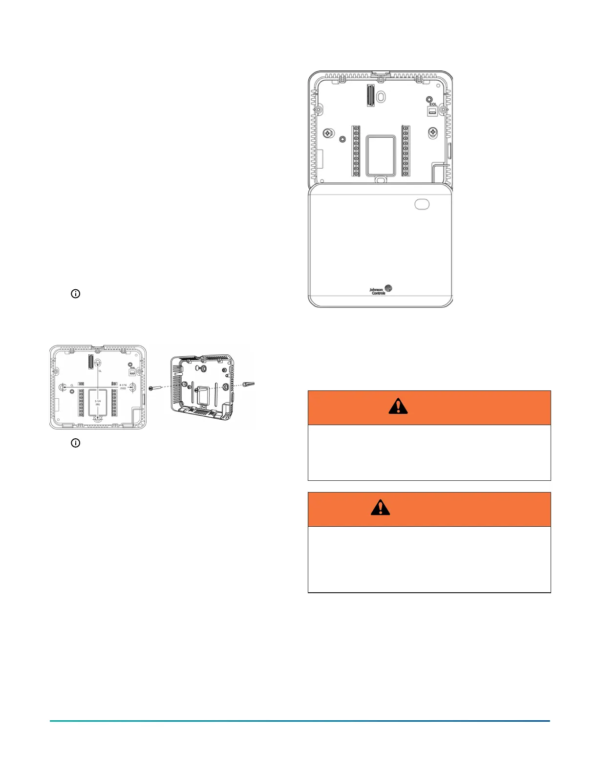
Note: When you mount the unit on the wall, you
can hang the front cover on the end of the back
cover as illustrated in Figure 4.
Figure 4: Hanging the thermostat controller front cover
Wiring
About this task:
When you replace an existing thermostat controller,
remove and label the wires to identify the terminal
functions.
WARNING
Risk of Electric Shock
Disconnect the power supply before making electrical
connections to avoid electric shock.
AVERTISSEMENT
Risque de décharge électrique
Débrancher l'alimentation avant de réaliser tout
raccordement électrique afin d'éviter tout risque de
décharge électrique.
TEC3000 Series Networked and Wireless Single- or Two-stage Economizer Thermostat Controllers Quick Start Guide 3