Note: Seal the hole in the wall with fireproof
material to prevent drafts from affecting the
ambient temperature readings.
4. For networked models, set the bus end-of-line (EOL)
termination switch to the desired location.
You can designate the thermostat controller as
the end of the Field Controller (FC) Bus and N2
Bus through the bus EOL termination switch.
The default position is OFF. If the thermostat
controller is at the end of a daisy chain of
devices on the FC Bus and N2 Bus, set the EOL
switch to the ON position. See Figure 3.
5. Reattach the thermostat controller cover to the
mounting base, bottom side first.
Important: Make sure you reattach the cover
that corresponds to its correct base. The CPU
board number needs to match the base board
number. Otherwise, an operation error occurs
after you reattach a cover and base that do not
belong together.
6. Use a 1/16 in. (1.5 mm) Allen wrench or Johnson
Controls T-4000-119 Allen-Head Adjustment Tool
(order separately) to reinstall the security screw
on the top of the thermostat controller cover. See
Figure 2 for security screw placement.
7. Remove the protective plastic cover sheet from the
display.
Important: If the display is dirty, gently wipe
it clean with isopropyl alcohol or ethyl alcohol.
Do not scrub hard as to avoid damaging the
surface. Do not use other cleaners such as
water, ketones, and aromatic solvents, since
they may damage the polarizer.
Notes:
- For VAV and two-pipe systems, connect the
valve to the heating output.
- Only one transformer is required for each TEC.
- Power to the AUX contact comes from the
reheat coil.
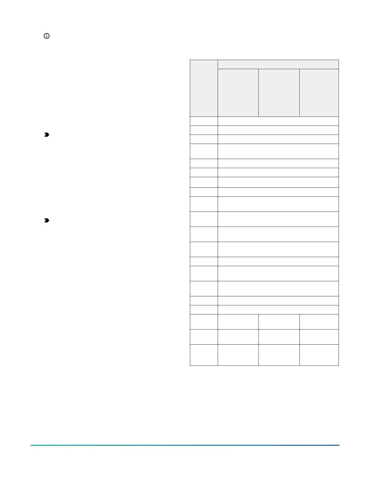
Terminal identification
Table 3: Terminal identification (See Wiring diagrams
for details)
FunctionTerminal
label
TEC3012,
TEC3013,
TEC311x
Floating FC/
VAV and On/
Off FC
1
1
TEC3312,
TEC3313
Floating FC/
VAV and On/
Off FC
1
TEC3612,
TEC3613
Floating FC/
VAV and On/
Off FC
1
24 V 24 VAC hot from transformer
FAN H Fan high
FAN M Fan medium
FAN L Fan on: single-speed, variable-speed, Fan low:
multi-speed
AUX Auxiliary binary output
AUX Auxiliary power input
2
HC/TRI
2
Cool or heat valve output common
COM 24 VAC common from transformer
CLG O Cool open (Floating), Cooling NC (On/Off),
Triac
CLG C Cool close (Floating), Cooling NO (On/Off),
Triac
HTG O Heat open (Floating), Heating NC (On/Off),
Triac
HTG C Heat close (Floating), Heating NO (On/Off),
Triac
RSEN Configurable analog input 1
COS Configurable analog input 2/Changeover
binary switch input
VSF Variable speed fan command, configurable 0
VDC to 10 VDC range
BI-2 Configurable binary input 2
BI-1 Configurable binary input 1
NET+ n/a Not connected Field bus+/
N2+
NET- n/a Not connected Field bus-/
N2-
NET COM n/a Not connected Isolated
common for
field bus
1 There is no support for an On and Off VAV.
2 HC/TRI on TB1 must be jumpered to COM on TB2 for low-
side switching or to 24 VAC on TB2 for high-side switching.
TEC3000 Series On/Off or Floating Fan Coil Thermostats Quick Start Guide4