14 Installation Guide
www.johnsoncontrols.com Issue Number: 2
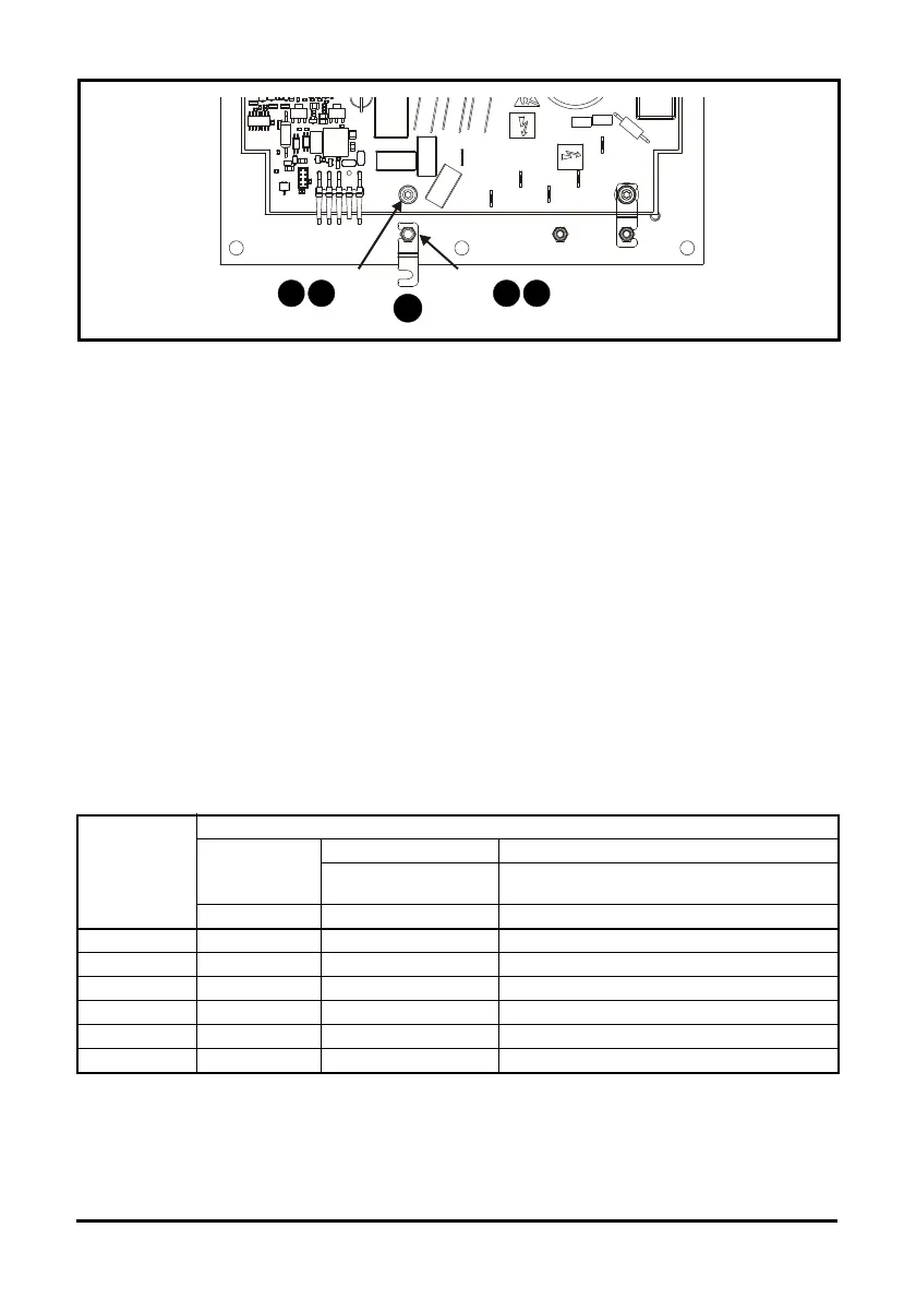
Figure 4-4 Removal of the internal MOV
To disconnect the internal MOV:
1. Loosen the plate M3 nut
2. Loosen PCB screw
3. Swivel the link to the position shown
4. Re-tighten M3 nut to 1Nm (8.9 lb in)
5. Re-tighten PCB screw to 1Nm (8.9 lb in)
4.3.3 Emissions compliance
An internal factory installed EMC filter is provided with all ratings, it is recommended that it is kept in
place unless there is a specific reason for removing it. (3) This internal filter reduces radio-
frequency emissions into the line power supply. When the motor cable is short, it permits the
requirements of EN61800-3:2004 to be met for the second environment with restricted distribution.
For longer motor cables, the filter continues to provide a useful reduction in emission level. When
used with any length shielded motor cable (up to the limit for the drive), it is unlikely that nearby
industrial equipment will be disturbed.
Installation of an additional external EMC filter as stated in Table 4-1 provides higher levels of
emissions compliance. If the application requires these levels of compliance then the external filter
must be installed in order to ensure compliance with EMC regulations such as the EC EMC
Directive, and to ensure the validity of the CE mark.
Table 4-1 Emissions compliance for VFD66 based on EMC filter configuration
*The typical leakage current of the low leakage filter is 3mA compared to the standard filter which
has a typical leakage current of 40mA.
Motor Cable
Length m (ft)
Filter and Switching Frequency
Internal filter
Only
Standard filter Low Leakage filter
Schaffner P/N:
FS6514-14-07
Schaffner P/N: FS6514-14-07-LL*
3kHz 3kHz 3kHz
1 (3) C4 C2 C2
5 (16) C4 C2 C2
10 (33) C4 C2 C3
15 (50) C4 C2 C3
25 (82) C4 C2 C3
50 (164) C4 C2 C3
3
Plate M3
nut
PCB
screw
2 5 1 4