VMA1400 Series Overview and Engineering Guidelines Technical Bulletin 17
Application Examples
Note: The examples in this document do not reflect all of the
possible questions and answers. These examples provide a basic
overview of wiring locations you might expect to see. They do not
define all available applications.
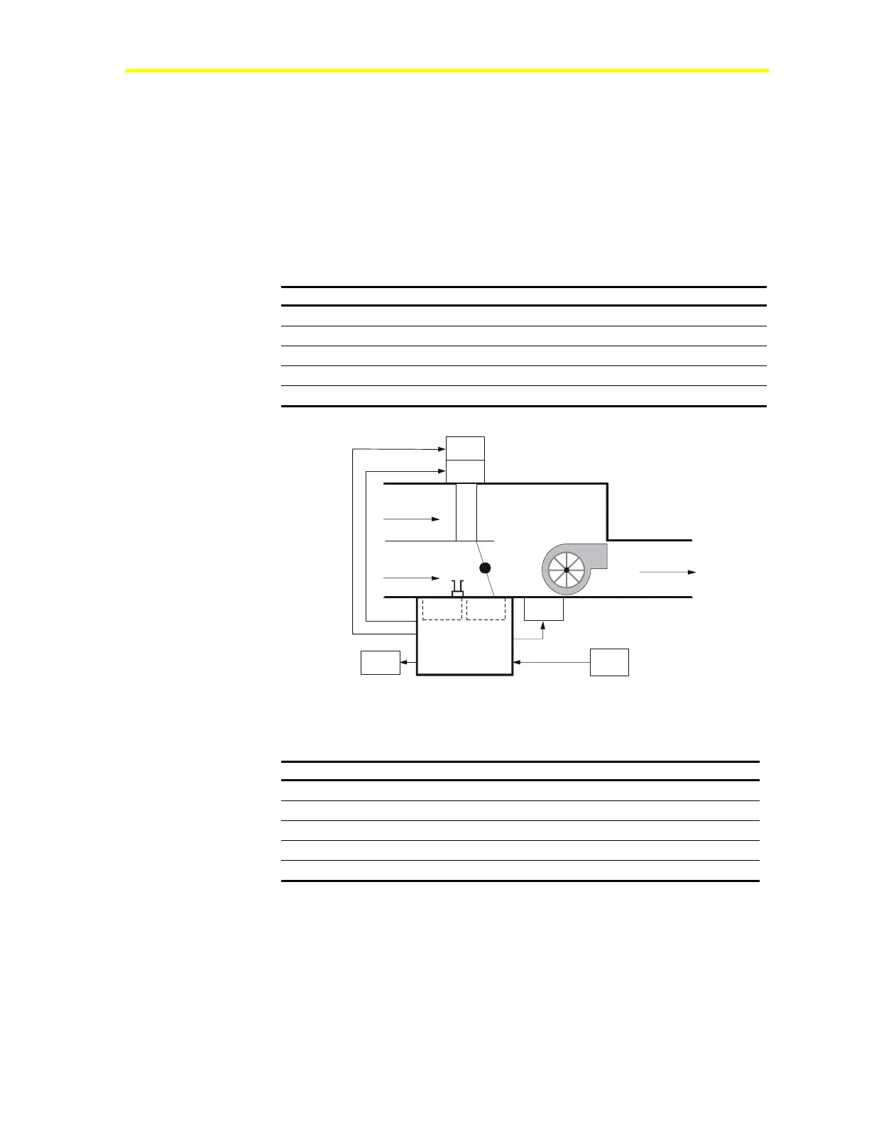
Single Duct Application Example 1
Table 6: Single Duct Example 1 Questions
HVAC PRO Software Questions Configuration Selections
VAV Box Type
Pressure Independent, Single Duct
Fan Type (R2)
Series/On-Off
Baseboard Heat Type
None
Box Heat Type (R3 and R4)
2-stages
Lighting (R1)
Start Stop Output (as shown in
Figure 4)
Plenum
Supply
Discharge
DPT1 DA1
T
G
R2
R1
R3
C1
H
TE1
Sample1
R4
Figure 3: Single Duct Example 1 Mechanical Flow Diagram
Table 7: Single Duct Example 1 Bill of Materials
Component Description Part Number
C1, DPT1, DA1
VMA AP-VMA1420-0
TE1
Temperature Sensor and Setpoint TE-6700 Series
R1
Lighting Relay GE-RR7
R2
Fan *
R3, R4
Reheat Relays *
* Box OEM manufacturers typically furnish fan relays and electric heat relays.