VMA1400 Series Overview and Engineering Guidelines Technical Bulletin 19
Single Duct Application Example 2
Table 8 illustrates the selections made through HVAC PRO software
for this example.
Table 8: Example 2 Questions
HVAC PRO Software Questions Configuration Selections
Control Strategy
Pressure Independent, Single Duct
Supply Damper Actuator (DA1)
Floating/3-wire
Fan Type (R)
Parallel Fan Temperature Controlled
Baseboard Heat Type (VA2)
Analog Output Valve
Box Heat Type (VA1)
Floating/3-wire
Warmup Initiation
Supply Air Temp Via a Hardware Input
Lighting Integration
No
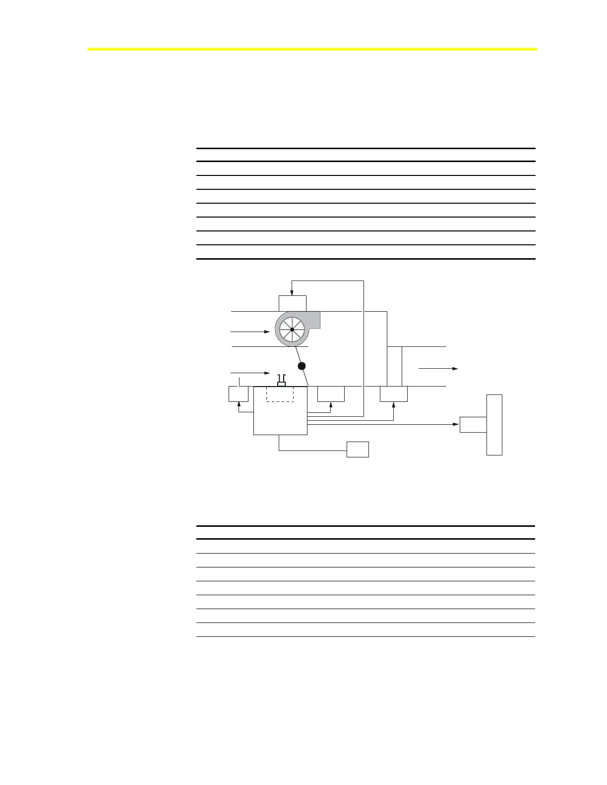
TE1
TE2
Plenum
Supply
Discharge
DPT1 DA1
H
T
G
R
B
A
S
E
B
D
VA2
VA1
C1
Sample3
Figure 5: Single Duct Example 2 Mechanical Flow Diagram
Table 9: Single Duct Example 2 Bill of Materials
Component Description Part Number
C1, DPT1
VMA AS-VMA1430-0
DA1
Damper Actuator Integrated with VAV box
TE1
Zone Temperature Sensor TMZ1600
TE2
Supply Air Temperature Sensor TE-6311P-1
VA1
Valve Actuator Box Heat VA-8020-1
VA2
Baseboard Heat Valve Actuator VA-8052
R
Fan *
* Box OEM manufacturers typically furnish fan relays and electric heat relays.
 Loading...