VMA1400 Series Overview and Engineering Guidelines Technical Bulletin 22
Single Duct Supply/Exhaust with BO Solenoid Application
Example
Table 12 illustrates the selections made through HVAC PRO for
Windows operating system for this example.
Note: This example only applies to HVAC PRO 8.05 or later.
Table 12: Example Questions
HVAC PRO Software Questions Configuration Selections
Control Strategy
Pressure Independent, Supply/Exhaust
with BO for Autocalibration Solenoid
Supply Actuator (DA1)
VMA Integrated Actuator
Fan Type
None
Exhaust Actuator (DA2)
Position Adjust Output (3-wire/floating)
Box Heat Type (VA1)
Analog Output
Baseboard Heat Type
None
Lighting Integration
None
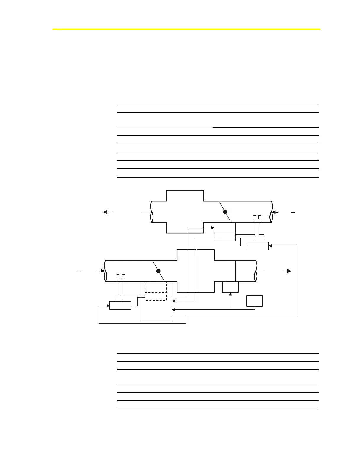
Supply
Air
to Zone
Exhaust Air
C1
TE1
DA1
DPT1
DA2
DPT2
from
H
T
G
VA1
supplyexhBO
SOL2
SOL1
c
c
nc
nc
no
no
Zone
Figure 8: Single Duct Supply/Exhaust with BO Solenoid Example Mechanical Flow Diagram
Table 13: Example Bill of Materials
Component Description Part Number
C1, DPT1, DA1
VMA AP-VMA1420-0
DPT2, DA2
External Actuator and Velocity
Pressure Sensor
M9104-AGS-2N
SOL1, SOL2
MAC 3-Way Solenoid Air Valves 35A-FW-24VAC*
VA1
Value Actuator Box Heat VA-8020-1
TE1
Temperature Sensor and Setpoint TE-6700 Series
* Part is available from Kele & Associates. For current information, consult the Web
site at www.kele.com.
 Loading...