VMA1400 Series Overview and Engineering Guidelines Technical Bulletin 24
Dual Duct Application Example
Table 14 illustrates the selections made through HVAC PRO software
for this example.
Note: This example only applies to HVAC PRO 8.0 or later.
Table 14: Example Questions
HVAC PRO Software Questions Configuration Selections
Control Strategy
Pressure Independent – Variable Box
Flow, Dual Duct
Discharge Air Sensor (TE2)
Yes
Cold Deck Actuator
VMA Integrated Actuator
Hot Deck Actuator (DA2)
Position Adjust Output (3-wire/floating)
Flow Sensor Locations (DPT1 and
DPT2)
Hot and Cold Deck Flow
Baseboard Heat Type
None
Lighting Integration
None
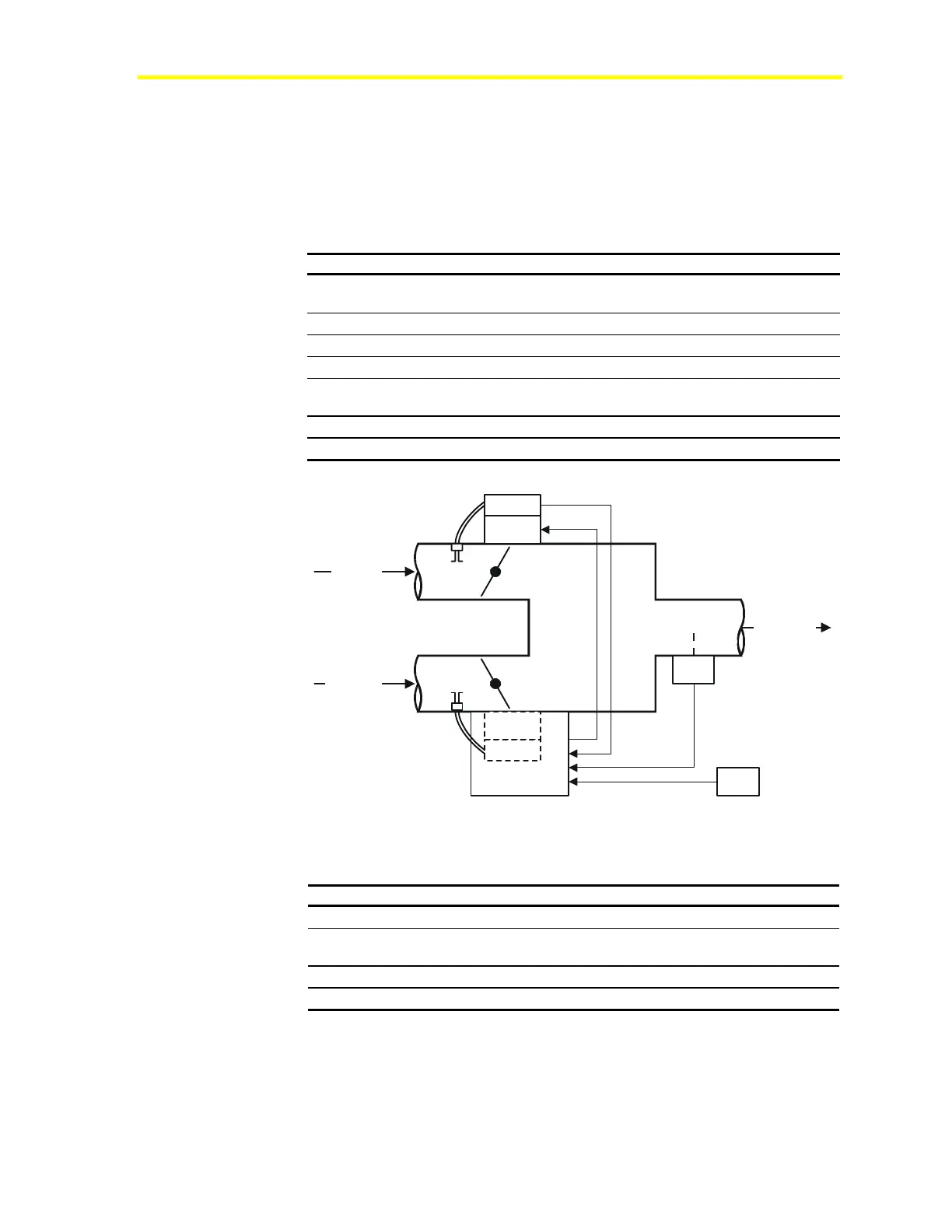
Cold Deck
Supply
Discharge
Hot Deck
Supply
Da2
DPT2
C1
Da1
DPT1
Te2
TE1
DD_Example
Figure 10: Dual Duct Example Mechanical Flow Diagram
Table 15: Example 2 Bill of Materials
Component Description Part Number
C1, DPT1, DA1
VMA AP-VMA1420-0
DPT2, DA2
External Actuator and Velocity
Pressure Sensor
M9104-AGS-2N
TE1
Temperature Sensor and Setpoint TE-6700 Series
TE2
Discharge Air Temperature Sensor TE-6300 Series
 Loading...