18 M Motor Actuators
—
Y20EBD Valve Linkage for M100 Motor Actuators
LOAD END
10° (AX)
Direction of
Drive Rotation
COM to CCW Shorted
Drive Shaft
Y20A1-15
Keyway
Zero Reference
Position
Direction of Drive
Rotation COM
to CW Shorted
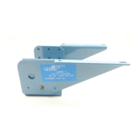
Figure 17: Actuator Zero Position
The actuators are factory set at zero position which is 10° clockwise from
square and for 90° clockwise travel as shown in Figure 17. Each 15° of
actuator rotation results in 0.1 inch (2.54 mm) of linear movement of the
rack assembly. The 90° actuator rotation provides 1/2 inch (12.7 mm) of
valve stem lift plus 0.1 inch (2.54 mm) of over travel.
Disconnect all control wires to the actuator. Refer to the technical bulletin
provided with the motor actuator for information on wiring the motor
actuator and related adjustments.
Connect only 24 VAC to terminals T1-T2. Be sure that power is off while
connections are made or changed. For quick reference, Table 2 provides
the connections for individual actuators.
Note: The M100C requires a Y199 tester to drive the motor actuator.
For stem up valves, make certain that the rack is assembled to the right of
the gear housing center.
Drive Down to Close Valves
1. Manually move the rack and spring housing assembly, connected to
the valve stem, to the full up position.
Y20A1-16
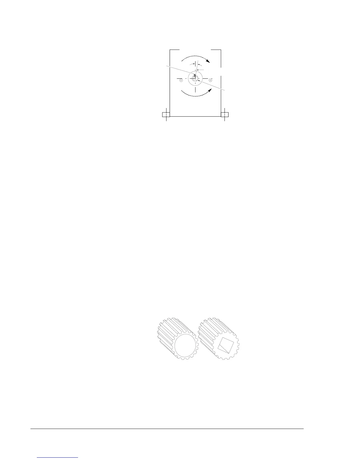
Figure 18: Pinion Gear Ends
2. Insert the pinion gear into the gear housing with the square hole end
(Figure 18) over the actuator shaft.
3. Replace the gear cover and tighten the gear cover screws. See
Figure 14.
Stem Up Two
Way Valve