M Motor Actuators
—
Y20EBD Valve Linkage for M100 Motor Actuators 7
The information obtained in the following steps will be used for the travel
adjustments later. The reason that these measurements are here is that it is
easier to take the measurements prior to installing the linkage and actuator
than after.
For valves with various lift requirements, the actuator will require a
change in travel by 15° for each additional 0.1 inch (2.54 mm) of lift
required.
To determine the lift required:
Valve Stem
Full Up
Valve Stem
Full Down
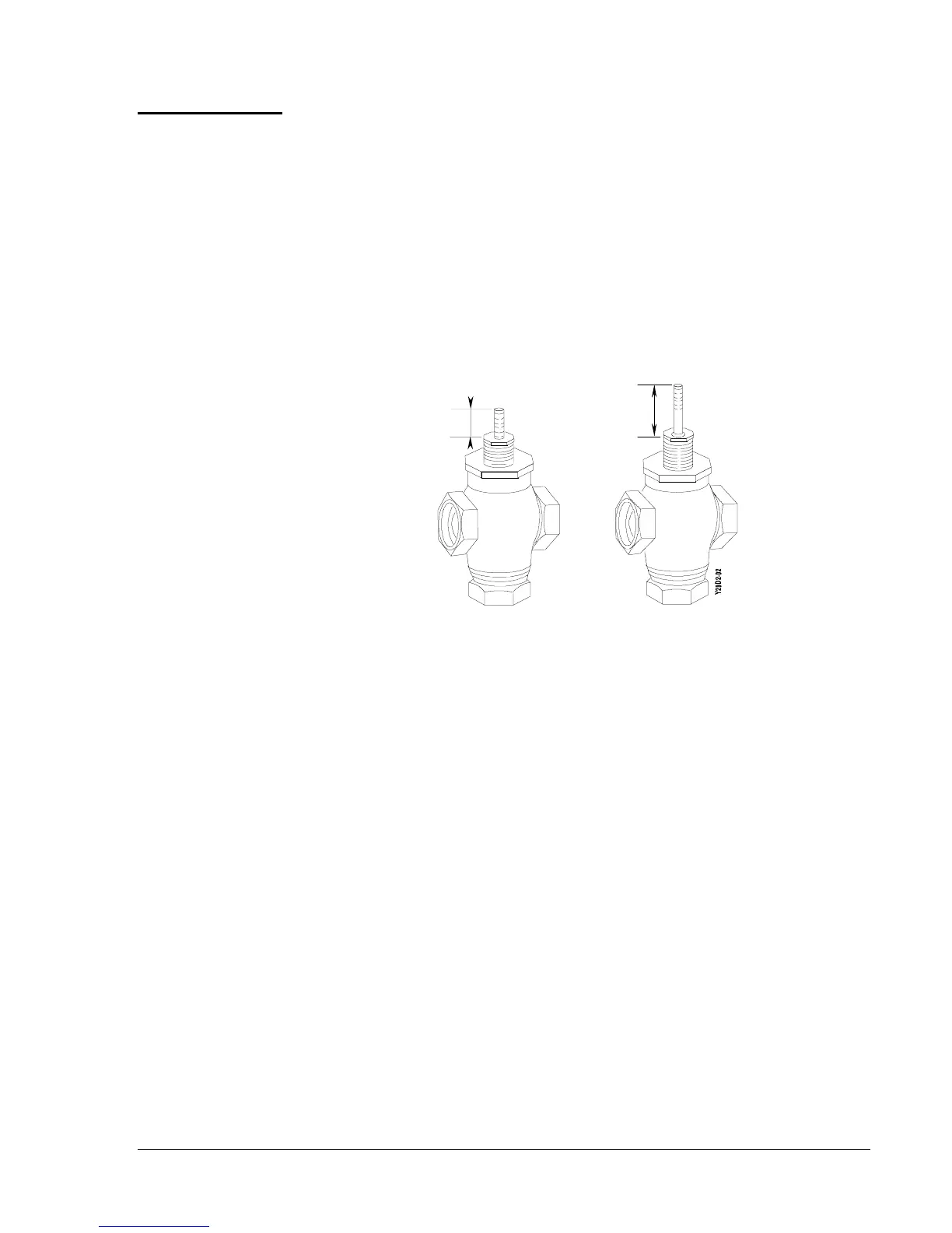
Figure 2: Stem Travel Measurement
1. Measure the valve stem length in the full down position as shown in
Figure 2.
2. Measure the valve stem length in the full up position as shown in
Figure 2.
3. Subtract the full down position from the full up position, this will
provide the valve lift.
4. Divide the valve lift by 0.1 inch.
5. Multiply the result by 15°.
6. Provide additional 15° rotation on 2-way valves and 30° additional
rotation on 3-way valves for over travel seating.
Note: Maximum actuator rotation is 270°, which allows up to 1.7 inches
lift on 2-way valves and 1.6 inches lift on 3-way valves.
Note: VT valves have only 5/16 inch lift which requires a reduction of
actuator travel by 25° from factory setting.
Record the value for use with the travel adjustments.
Configuration
and Mounting
Valve Lift