The connector on the PC has Male pins, therefore the mating cable needs to terminate in a DB25/F
(Female pin) connector.
Table 13: RS-232 pin assignments - DB9 PC signal set (most laptops)
Pin Description Pin Description
Pin 1
Received line Signal Detector (Data Carrier
Detect)
Pin 2 Received Data
Pin 3 Transmit Data Pin 4 Data Terminal Ready
Pin 5 Signal Ground Pin 6 Data Set Ready
Pin 7 Request To Send Pin 8 Clear To Send
Pin 9 Ring Indicator
The connector on the PC has male pins; therefore, the mating cable needs to terminate DB9/F
(female pin) connector.
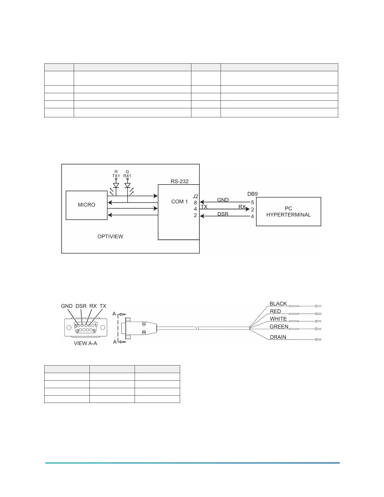
Figure 5: Communications block diagram
A serial cable to go from the OptiView Control Panel to the serial port is available from the parts
center (P/N 075-90490-230).
Figure 6: OptiView panel to PC serial cable
Table 14: Wiring positions
Signal DB9 Color
TX Position 2 Black
RX Position 3 Red
DSR Position 4 White
GND Position 5 Green
53Model YD Mod D with OptiView Control Center
 Loading...


