A.0500.501 – IM-TGGS/05.01 EN (03/2013)
4.6 Mechanical seal
Guidelines for assembly and adjustment of the mechanical seal – pump types GS.
4.6.1 General
• Allpersonnelresponsibleformaintenance,inspectionandassemblymustbe
adequately qualified.
• Usespecicinstructionscomingwiththemechanicalsealwhichistobeassembled/adjusted.
• Theassemblingandadjustingofmechanicalsealsmustbeperformedinacleanworkshop.
• Usetechnicallyappropriatetoolsthatareingoodcondition.Handlethemcorrectly.
4.6.2 Preparation
Check if the mechanical seal to be mounted has the appropriate size and construction and verify if
it can be assembled. The short EN12756 (DIN24960) single mechanical seal can be built in. The
mechanical seal is set against the rotor shoulder.
4.6.3 Special tools
• Conicalprotectionbush(9010)
•Shammy
4.6.4 General instructions during assembly
• Donottouchthemechanicalsealfaceswithhandorngers.Fingerprintscanmakethe
mechanical seal untight. Clean the seal faces if necessary. Use a shammy.
• Ifthemechanicalsealfacesaremadeofnonself-lubricatingmaterial,itisrecommendedto
lubricate the faces a little with the pumped liquid or with thin oil. Do not use grease!
• LubricatetheO-ringswhenassembling.Takecareofcomplianceofthelubricantandthe
rubber material. Never use mineral oil using EP rubber O-rings.
• WhenttingPTFEsealingstheshaftmustbeverysmooth.AssemblyofsolidPTFEsealingscan
be facilitated by heating the stationary ring in water at 100°C during 15 minutes.
Pre-assemble the rotary ring on a dummy shaft and heat both ring and shaft in water at 100°C
during 15 minutes. Then let everything cool off. To be tight, PTFE seals must rest for appox.
2 hours so that the O-ring remains in its new shape.
• Incaseswherethemechanicalsealisprovidedwithxingscrewstoxtherotatingparton
the shaft, it is recommended to screw out the fixing screws, degrease both holes and screws
and lock them with Loctite (usual type 241 or heat-resistant type 648).
4.6.5 Assembly of the rotating part
• Lubricatetheshaftalittlewithalubricant.
Attention for EP rubber: do not use mineral oil!
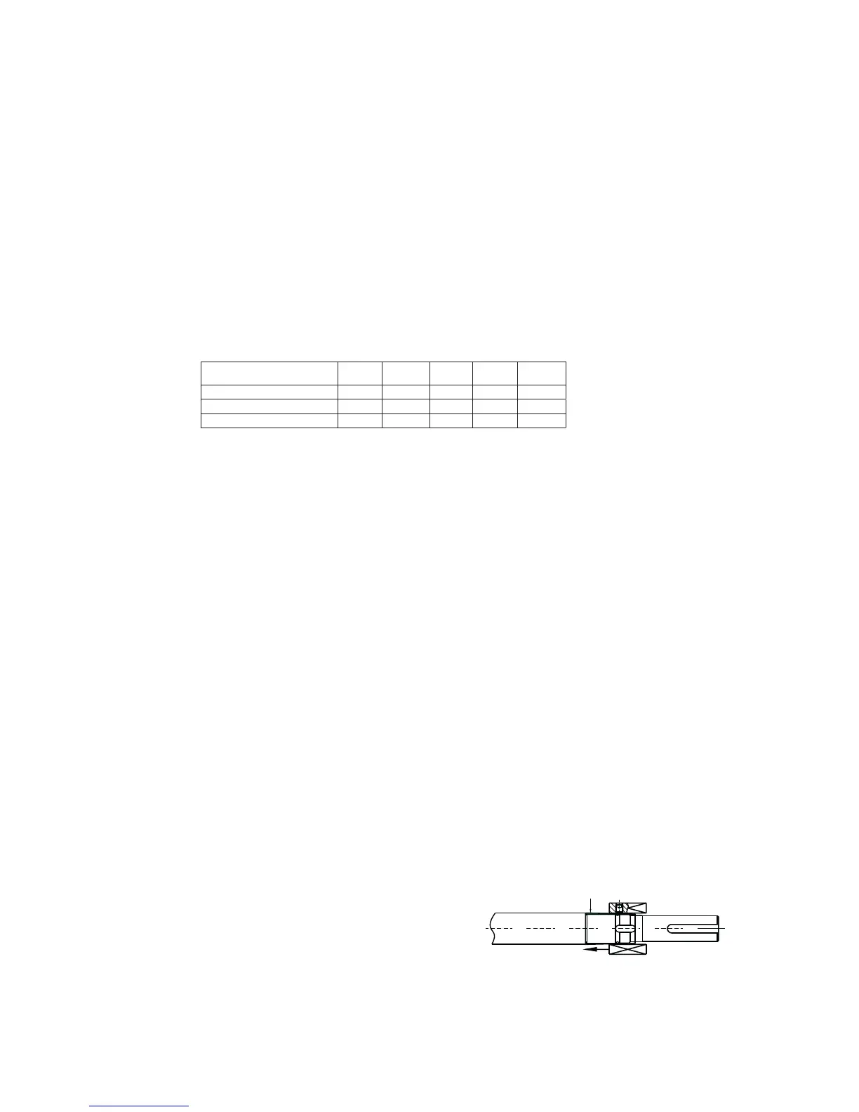
• Protectthesharpedgesoftheshaftwith
tape or another protecting tool.
• Useaconicalassemblingbush(9010)
on the shaft step (see figure).
• Pushtherotatingpartsagainst
the rotor shoulder.
• Providethesetscrewswithadropheat-resistantLoctiteandtthesetscrewsintherotating
part. Tighten the screws.
TG GS pump size
2-25
2-32
6-40
15-50
23-65
58-80
86-100
185-125
Shaft diameter 18 22 35 40 55
Short EN12756 (DIN24960) KU018 KU022 KU035 KU040 KU055
L-1K (short KU) 37.5 37.5 42.5 45 47.5
Dimensions in mm



 To Next Page