56
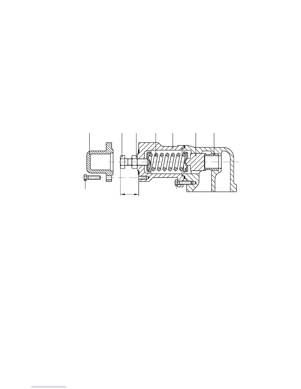
7310
7050 7320 7330 7150
7040
7010 7110
7300
H
A.0500.501 – IM-TGGS/05.01 EN (03/2013)
4.8 Relief valve
• Thereliefvalvemaynotbedisassembledbeforethespringhasbeenreleasedcompletely
• Before releasing the spring, measure the position of the adjusting bolt, so that the
spring afterwards can be adjusted to its original opening pressure
4.8.1 Disassembly
• Undothescrews(7310)andthecover(7050).
• Measureandrecordtheexactpositionoftheadjustingbolt(7320).(SeedimensionH).
• Loosennut(7330)andadjustingscrew(7320)untilthespring(7150)hasbeencompletely
released.
• Removespringcasing(7040)bylooseningthescrews(7300).
• Spring(7150),valve(7010)andvalveseat(7110)arenowaccessible.
4.8.2 Assembly
• Checkthesealingfaceofbothvalveseat(7110)andvalve(7010).
• Incaseofaslightlydamagedsurface,thiscanberubbedwithanappropriateemerypaste.
In case of severe damage however, valve seat (pay attention to shrink fit) and valve must be
replaced.
• Alwaysmountacorrecttypeofspringwiththeoriginaldimensionsandanappropriate
adjusting screw (see section 3.17.3).
• Fitspringcasing(7040)andbolts(7300).
• Fitadjustingscrew(7320)andnut(7330),screwingtheadjustingscewtomeasured
distance H.
• Fixthispositionbytighteningthenut(7330).
Remark: When another type of spring and/or adjusting bolt is mounted, the opening pressure
of the relief valve must be adjusted hydraulically.
• Fitcover(7050)andscrews(7310).
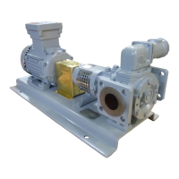
Assembly and disassembly of the safety relief valve



 To Next Page