Page Issue A
Chapter - Optional Equipment4:2
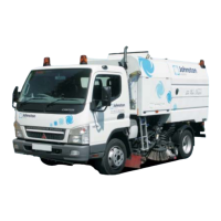
CN101 - Maintenance
4WS Bleeding
The following outlines the correct procedure for the removal of air from the Johnston CN101 rear
hydraulic 4 wheel steering (4WS) cylinder.
Should for any reason air be introduced into the 4WS hydraulic system (hose replacement, etc.)
the following procedure must be undertaken to ensure that the 4WS system functions safely and
as intended.
Air in the rear steering cylinder may result in inconsistent control and poor centralisation of the rear
wheels.
Procedure
Safe working practices should be adhered to throughout.
1. Start the engine, raise the hopper and support on the prop. Activate the 4WS and turn the
steering wheel fully to the left hand lock (rear wheels will point to the right hand side). Stop the
engine; the rear steering cylinder is now at its maximum stroke, see gure one.
2. Remove the cover panel above the hydraulic control located on the right hand side of the
machine (held by ve 13mm headed xings). Fit the tee piece and test point between the hose
and adaptor at the HB port on the 4WS hydraulic valve block and tighten securely with the test
point facing vertically, see gure two.
3. From the hydraulic test kit use one of the test hoses to connect between the test point at HB
on the 4WS hydraulic valve block, see gure three. and the test point at port PS on the charge
pressure connector of the driving pump, see gure four.
4. Start the engine.
5. Whilst taking all necessary precautions to protect the any personnel and the surrounding area
from any air and oil that is released. Slowly undo the banjo connector bolt on the rear steering
cylinder until any trapped air and oil is seen to be released from the connection. Repeat several
times or until no air is seen to be expelled and then retighten the connection bolt ensuring
correct orientation of the hose.
6. Stop the engine; disconnect the test hose from the 4WS hydraulic valve block and the charge
pressure connector of the driving pump. Ret the protective covers to both test points.
7. Start the engine, activate and operate the 4WS - check the circuit for leaks – Stop the engine.
Warning
Starting the engine will charge the 4WS hydraulic valve block output HB to a pressure of
25 bar. Any air trapped within the system will also be compressed to this pressure.
Suitable precautions must be applied when venting the circuit in the following steps.