10 99213_UM_TR710_D
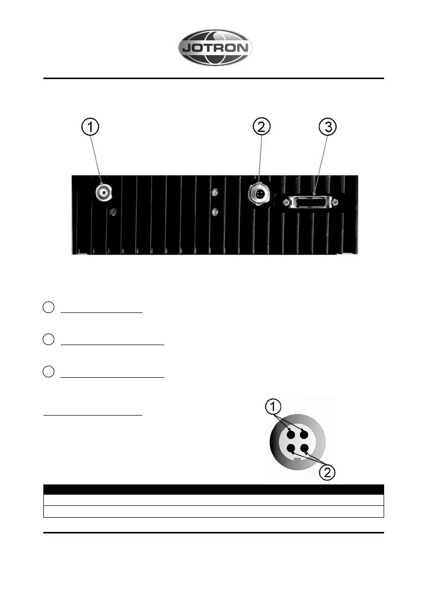
Transceiver rear connections
Figure B: Rear view, TR-710.
1 Antenna Connector.
TNC-connector for antenna input/output.
2 Power-supply Connector.
This connector is connected to the external DC supply (+11 to +15V).
3 Multifunction Connector.
For details refer to technical handbook.
Power supply connector
Figure C: Power supply connector, female.
Table 1: functional description of the power
supply connector.
Pin pair nr. Signal Function description
1 U_BAT Supply voltage (11-15V)
2 GND Common ground.
Table 1: